
User`s manual


D-7
Appendix D SAS-836TQ Backplane Specications
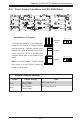
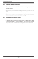
D-6 Front Jumper Locations and Pin Denitions
Explanation of Jumpers
To modify the operation of the backplane,
jumpers can be used to choose between
optional settings. Jumpers create shorts
between two pins to change the function
of the connector. Pin 1 is identied with
a square solder pad on the printed circuit
board.
Note: On two pin jumpers, "Closed" means
the jumper is on and "Open" means the
jumper is off the pins.
Connector
Pins
Jumper
Setting
3 2 1
3 2 1
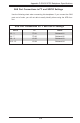
General Jumper Settings
Jumper Jumper Settings Note
JP35
Open: Default
Closed: Reset
9072 Chip Reset #1
JP50
Open: Default
Closed: Reset
9072 Chip Reset #2
JP48
JP46
JP13
JP10
JP60
JP58
JP56
JP54
Y2
Y1
F15F16
F9
F14
JP68
BZ1
C102
C121
C155
C158
C23
C284
C29
C122
C159
C162
C171
C174
C177
C227
C245
C257
C258
C267
C275
C80
C100
C170
C173
C176
C179
C195
C226
C229
C79
C285
C197
C198
C199
C200
C201
C202
C203
C204
C3
C44
C45
C5
C84
C85
C139
C88
C86C89
C130
C148
C172
C175
C178
F1
F2
F3
F4
JP18
JP50
JP61
JP62
JP63
JP64
R443
R459
R458
R437
R439
R455
R325
R246R105
R194 R324
R308
R351
R339R338
R314
R393
R222
R332
R353
R169
R170
R249
R268
R273
JP100
JP25
JP45
JP99
JP84
D46
D85
D83
D79
D73
D72
D70
D69
D66
D64
D61
D60
D55
JP106
JP95
JP52
U67
JP69
J7
J6
J5
J8J32
J30
J24
J23
J25 J16
J14
J12
J10
J29
J26
J22
JP26
JP47
U34
1
4
1
4
1
4
4
1
41
4
1
41
49
48 33
32
17
49
48 33
32
17
1
+
+
+
+
+
+
+
+
+
+
+
+
+
+
+
+
+
1
1
1
BAR CODE
UPGRADE#2
FAN#1
FAN#2
1
1
1
1
ACT15
1
ACT14
ACT13
ACT12
ACT11
ACT10
ACT9
ACT8
ACT3
ACT2
ACT1
ACT0
JP97:FAN#1 SELECT
JP98:FAN#2 SELECT
JP99:FAN#3 SELECT
2-3:NO FAN
1-2:WITH FAN
JP100:FAN#4 SELECT
1
OFF:NO FAN
ON:WITH FAN
JP64:FAN#4 SELECT
JP63:FAN#3 SELECT
JP62:FAN#2 SELECT
JP61:FAN#1 SELECT
UPGRADE#1
#0#1
#2
#3
#4
#5
#7 #6
#14
#15
#13 #12
#11
#10
#9
#8
I2C#4
I2C#3
I2C#2
I2C#1
BUZZER RESET
REV 3.2
SAS836TQ
D53 D54D3 D36
CA ACA CA
C
C
A
CA CA
FAN#4
FAIL
FAN#3
FAIL
FAN#2
FAIL
FAIL
FAN#1
ALARM#1 ALARM#2 +5V +12V
JP61
JP98
JP97
JP62
JP99
JP100
JP84
JP50
JP63
JP64
JP35