
User`s manual


D-5
Appendix D SAS-836TQ Backplane Specications
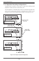
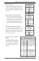
#10., #11., #12., #13. Sideband
Headers
The sideband headers are desig-
nated JP66, JP68, JP75 and JP77.
are for enclosure management
of the SGPIO mode connection.
See the table to the right for pin
denitions.
Sideband Headers
(JP66, JP68, JP75 and JP77)
Pin # Denition Pin # Denition
2 SGPIO:
SDIN
I
2
C:
Backplane
Addressing
(SB5)
1 Controller ID (SB6)
4 SGPIO:
SDOUT
I
2
C: Reset
(SB4)
3 GND (SB2)
6 GND (SB3) 5 SGPIO: SLOAD
I
2
C:SDA (SB1)
8 Backplane
ID (SB7)
7 SGPIO: SCLOCK
I
2
C:SCL (SB0)
10 No Connec-
tion
9 No Connection
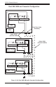
Backplane
Main Power
4-Pin Connector
(JP10, JP13, JP46,
and JP48)
Pin# Denition
1
+12V
2 and 3 Ground
4 +5V
#9. Backplane Main Power Connectors
The 4-pin connectors, designated JP10,
JP13, JP46, and JP48, provide power to the
backplane. See the table on the right for pin
denitions. All four of these connectors must
be used at the same time.
#4. Fan Connectors
The 4-pin connectors, designated JP54, JP56,
JP58 and JP60, provide power to the fans. See
the table on the right for pin denitions. These
4-pin connectors are compatible with 3-pin and
4-pin fans.
Fan Connectors
(JP54, JP56, JP58,
and JP60)
Pin# Denition
1 Ground
2 +12V
3 Tachometer
4 No connection
#5., #6., #7., #8. I
2
C Y-Cable Connectors
The I
2
C Y-cable connectors, designated JP37,
JP52, JP95, and JP96, are for enclosure
management of the I
2
C mode connection.
These connectors are used only if the I
2
C is
not embedded into the sideband connectors.
See the table on the right for pin denitions.
I
2
C Y-Cable
Connector
Pin Denitions
(JP37, JP52, JP95,
and JP96)
Pin# Denition
1 Data
2 Ground
3 Clock
4 No Connection