
User`s manual


C-6
SC836 Chassis Manual
C-6 Front Jumper Locations and Pin Denitions
CB154
PRI_J0
PRI_J1
PRI_J2
SEC _J 0 SEC_J 1
SEC _J 2
J1 7
J1 6
SEC_M ODE5
SEC_M ODE4
PRI_MODE5
PRI_MODE4
PRI_IPMI
SEC_IPMISEC_I2C
PRI_I2C
SEC_FLASH
PRI_FLASH
SEC_EX P
PRI_EXP
FA N4
FA N3
FA N2
FA N1
BUZZER 1
5V_L ED
12V_ LED
OVERHEATFA IL1 FA NFAIL1
BUZZER _ENB1
FAN_ALERT_EN1
J P 10 6
J P 10 5
PW R3 PW R2
PW R1 PW R0
REMOTE_FAN_FAIL_SCOKET
CA CA
CA
CA
GNDGND
+12V
+5V
GNDGND +12V
+5V
GNDGND
+12V
+5V
GNDGND
+12V
+5V
W W N
REV 1.01
SA S83 6EL
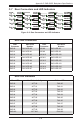
General Jumper Settings
Jumper Jumper Settings Note
PRI_MODE4 1-2
Factory Setting
Do not change
PRI_MODE5 2-3
Factory Setting
Do not change
SEC_MODE4 1-2
Factory Setting
Do not change
SEC_MODE5 2-3
Factory Setting
Do not change
CB154
PRI_J0
PRI_J1
PRI_J2
SEC_J0 SEC_J1
SEC_J2
J17
J16
SEC_MO DE5
SEC_MO DE4
PRI_MO DE5
PRI_MO DE4
PRI_IPMI
SEC_IPMISEC_I2C
PRI_I2C
SEC_FLASH
PRI_FLASH
SEC_EXP
PRI_EXP
FAN4
FAN3
FAN2
FAN1
BUZZER1
5V_LED
12V_LED
OVERHEATFA IL1 FANFAIL1
BUZZER_ENB1
FAN_ALERT_EN1
JP106
JP105
PW R3 PW R2
PW R1 PW R0
REM OTE_FAN_FAIL_SCOKET
CA CA
CA
CA
GNDGND
+12V
+5V
GNDGND +12V
+5V
GNDGND
+12V
+5V
GNDGN D
+12V
+5V
W W N
REV 1.01
SAS836EL
SEC_Mode5
SEC_Mode4
Fan Alert Enable
CB154
PRI_J0
PRI_J1
PRI_J2
SEC_J0 SEC_J1
SEC_J2
J17
J16
SEC_M ODE5
SEC_M ODE4
PRI_M ODE5
PRI_M ODE4
PRI_IPM I
SEC_IPM ISEC_I2C
PRI_I2C
SEC_FLASH
PRI_FLASH
SEC_EXP
PRI_EXP
FAN4
FAN3
FAN2
FAN1
BUZZER1
5V_LED
12V_LED
OVERHEATFAIL1 FANFAIL1
BUZZER_ENB1
FAN _ALERT_EN1
JP106
JP105
PW R3 PW R2
PW R1 PW R0
REM OTE_FAN_FAIL_SCOKET
CA CA
CA
CA
GNDGND
+12V
+5V
GNDGND +12V
+5V
GNDGND
+12V
+5V
GNDGND
+12V
+5V
W W N
REV 1.01
SAS836EL
PRI_Mode5
PRI_Mode4
Remote Fan
Fail
Buzzer Enable
Figure C-3: Backplane Jumper Settings
Explanation of Jumpers
To modify the operation of the backplane,
jumpers can be used to choose between
optional settings. Jumpers create shorts
between two pins to change the function
of the connector. Pin 1 is identied with
a square solder pad on the printed circuit
board. Note: On two pin jumpers, "Closed"
means the jumper is on and "Open" means
the jumper is off the pins.
Connector
Pins
Jumper
Setting
3 2 1
3 2 1