
User`s manual


C-3
Appendix C SAS-836EL Backplane Specications
Jumper Settings and Pin Denitions
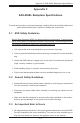
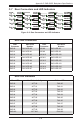
C-4 Front Connectors and Jumpers
Front Connectors
1. CD-ROM/Floppy Drive Power: JP105
and JP106
2 and 3. Primary and Secondary I
2
C
connectors (optional)
4. Power Connectors: PWR0, PWR1,
PWR2, and PWR3
5. Primary and Secondary Expander
Chip
6. Primary and Secondary Flash Chip
7. EPP Connectors: J16 and J17
8. Fan Connectors: Fan2, Fan3, and
Fan4 (Fan1 is not used)
9. SAS Connectors: PRI_J0
10. SAS Connectors: PRI_J1
11. SAS Connectors: PRI_J2
12. SAS Connectors: SEC_J1 (not avail-
able in EL1 single port backplanes)
13. SAS Connectors: SEC_J0 (not avail-
able in EL1 single port backplanes)
14. SAS Connectors: SEC_J2 (not avail-
able in EL1 single port backplanes)
CB154
PRI_J0
PRI_J1
PRI_J2
SEC _J 0 SEC _J 1
SEC _J 2
J1 7
J1 6
SEC_M ODE5
SEC_M ODE4
PRI_MODE5
PRI_MODE4
PRI_IPMI
SEC_IPMISEC_I2C
PRI_I2C
SEC_FLASH
PRI_FLASH
SEC_EX P
PRI_EXP
FA N4
FA N3
FA N2
FA N1
BUZZER 1
5V_L ED
12V_ LED
OVERHEATFA IL1 FA NFAIL1
BUZZER _ENB1
FAN_ALERT_EN1
J P 10 6
J P 10 5
PW R3 PW R2
PW R1 PW R0
REMOTE_FAN_FAIL_SCOKET
CA CA
CA
CA
GNDGND
+12V
+5V
GNDGND +12V
+5V
GNDGND
+12V
+5V
GNDGND
+12V
+5V
W W N
REV 1.01
SA S83 6EL
4
9
8
1
7
1
6
22
55
6
7
8
3
3
88
11
14
1213
10
PRI_J0
PRI_J1
PRI_J2
J1 6
PRI_MODE5
PRI_MODE4
PRI_IPMIPRI_I2C
PRI_FLASH
PRI_EXP
FA N4
FA N3
FA N2
FA N1
BUZZER 1
5V_L ED
12V_ LED
OVERHEATFA IL1 FANFAIL1
BUZZER _ENB1
FAN_ALERT_EN1
J P 10 6
J P 10 5
PW R3 PW R2
PW R1 PW R0
CA CA
CA
CA
GNDGND
+12V
+5V
GNDGND +12V
+5V
GNDGND
+12V
+5V
GNDGND
+12V
+5V
W W N
REV 1.01
SA S83 6EL
REMOTE_FAN_FAIL_SCOKET
2
11
4
5
6
7
9
3
8
8
88
10
11
Figure C-1: SAS-836EL2 Backplane
Figure C-2: SAS-836EL1 Backplane