
User`s manual


E-6
SC836 Chassis Manual
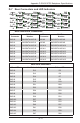
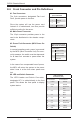
Front Pane LEDs
LED STATE SPECIFICATION
Power LED ON Activity in Power Control Board
Fan1 Fail ON Failure in Fan 1
Fan2 Fail ON Failure in Fan 2
E-7 LED Indicators
AA
AA
AA
REV 1.00
JBPWR2
Power LED
Fan2 Fail
Fan1 Fail
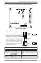
E-8 Power Card Placement
Front Processor Locations
Secure the Board to
these four holes
Figure E-3: LEDs
Figure E-4: Fastening the Power Card