
User`s manual


E-4
SC836 Chassis Manual
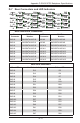
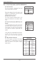
Power Fault Connector
(MCU Power On Switch)
Pin# Denition
1 Power Fault #1
2 Power Fault #2
3 Power Fault #3
4 Reserved
E-5 Front Connector and Pin Denitions
#3. Power Fault Connector (MCU Power On
Switch)
In normal operating mode, power is governed
by the MCU (Micro Controller Unit). As a ser-
curity measure, the switch must be depressed
for at least four seconds to power down the
system.
In the case of an unexpeceted loss of power,
the MCU will return the system to the power
state it was in at the time when power was
lost.
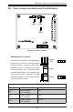
LED and Switch
Connectors (JF1)
Pin # Denition Pin # Denition
1 Power 2 Ground
3 Reset 4 Ground
5 Vcc 6 Power Fail
LED
7 Vcc 8 OH/Fan Fail
LED
9 Vcc 10 NIC2
11 Vcc 12 NIC1
13 Vcc 14 HDD LED
15 Vcc 16 Power LED
17 x (Key) 18 x (Key)
19 NMI 20 Ground
#4. LED and Switch Connector
The LED Header and Switch Connector,
designated JF1, is cabled directly to the front
panel. This allows the front panel to display
system status.
#1. Fan Connectors
The 3-pin connectors, designated Fan1 and
Fan2, provide power to the fans.
Since the system will use the power card
instead of a motherboard, two fans provide
sufcient cooling for the server.
Fan Connectors
(Fan1 and Fan42
Pin# Denition
1 Ground
2 +12V
3 Tachometer
#2. Main Power Connector
The 12-pin connector provides power to the
card to be distributed to the chassis compo-
nents.