SUPER ® SC836 Chassis Series SC836TQ - R800B SC836E1 - R800B SC836E2 - R800B SC836TQ - R710B User’s Manual 2.
SC836 Chassis Manual The information in this User’s Manual has been carefully reviewed and is believed to be accurate. The vendor assumes no responsibility for any inaccuracies that may be contained in this document, makes no commitment to update or to keep current the information in this manual, or to notify any person or organization of the updates. Please Note: For the most up-to-date version of this manual, please see our web site at www.supermicro.com. Super Micro Computer, Inc.
Preface Preface About This Manual This manual is written for professional system integrators and PC technicians. It provides information for the installation and use of the SC836 3U chassis. Installation and maintenance should be performed by experienced technicians only. Supermicro’s SC836 3U chassis features a unique and highly-optimized design for dual-core Xeon platforms. The chassis is equipped with a redundant 800W high efficiency power supply.
SC836 Chassis Manual Manual Organization Chapter 1 Introduction The first chapter provides a checklist of the main components included with this chassis and describes the main features of the SC836 chassis. This chapter also includes contact information. Chapter 2 System Safety This chapter lists warnings, precautions, and system safety.
Preface Compatible Backplanes This section lists compatible cables, power supply specifications, and compatible backplanes. Not all compatible backplanes are listed. Refer to our Web site for the latest compatible backplane information.
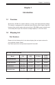
SC836 Chassis Manual Table of Contents Chapter 1 Introduction 1-1 Overview.......................................................................................................... 1-1 1-2 Shipping List..................................................................................................... 1-1 Part Numbers................................................................................................... 1-1 1-3 Chassis Features..............................................................
Preface 5-3 Removing the Chassis Cover.......................................................................... 5-2 5-4 Installing the Hard Drives................................................................................. 5-3 Removing Hard Drive Trays from the Chassis................................................ 5-3 Installing a Hard Drive to the Hard Drive Tray................................................ 5-3 5-5 Installing the Motherboard.................................................
SC836 Chassis Manual Chapter 7 Rack Installation 7-1 Overview.......................................................................................................... 7-1 7-2 Unpacking the System..................................................................................... 7-1 7-3 Preparing for Setup.......................................................................................... 7-1 Choosing a Setup Location.............................................................................
Chapter 1 Introduction Chapter 1 Introduction 1-1 Overview Supermicro’s SC836 3U chassis features a unique and highly-optimized design. The chassis is equipped with a redundant high efficiency power supply. High performance fans provide ample optimized cooling for FB-DIMM memory modules and 16 hot-swap drive bays offer maximum storage capacity in a 3U form factor.
SC836 Chassis Manual 1-3 Chassis Features The SC836 3U high performance chassis includes the following features: CPU Support The SC836 Chassis supports a DP Dual-core Xeon processor. Please refer to the motherboard specifications pages on our Web site for updates on supported processors for this chassis Hard Drives The SC836 Chassis features 16 slots for U320 SCSI or SAS/SATA drives. These drives are hot swappable.
Chapter 1 Introduction 1-4 Contacting SuperMicro Headquarters Address: Super Micro Computer, Inc. 980 Rock Ave. San Jose, CA 95131 U.S.A. Tel: +1 (408) 503-8000 Fax: +1 (408) 503-8008 Email: marketing@supermicro.com (General Information) support@supermicro.com (Technical Support) Web Site: www.supermicro.com Europe Address: Super Micro Computer B.V. Het Sterrenbeeld 28, 5215 ML 's-Hertogenbosch, The Netherlands Tel: +31 (0) 73-6400390 Fax: +31 (0) 73-6416525 Email: sales@supermicro.
SC836 Chassis Manual 1-5 Returning Merchandise for Service A receipt or copy of your invoice marked with the date of purchase is required before any warranty service will be rendered. You can obtain service by calling your vendor for a Returned Merchandise Authorization (RMA) number. When returning to the manufacturer, the RMA number should be prominently displayed on the outside of the shipping carton, and mailed prepaid or hand-carried.
Chapter 2 System Safety Chapter 2 System Safety 2-1 Overview This chapter provides a quick setup checklist to get your chassis up and running. Following the steps in order given should enable you to have your chassis setup and operational within a minimal amount of time. These instructions assume that you are an experienced technician, familiar with common concepts and terminology.
SC836 Chassis Manual 2-4 Electrical Safety Precautions Basic electrical safety precautions should be followed to protect yourself from harm and the SC836 from damage: • • • • • • • • Be aware of the locations of the power on/off switch on the chassis as well as the room’s emergency power-off switch, disconnection switch or electrical outlet. If an electrical accident occurs, you can then quickly remove power from the system. Do not work alone when working with high voltage components.
Chapter 2 System Safety • DVD-ROM Laser: CAUTION - this server may have come equipped with a DVD-ROM drive. To prevent direct exposure to the laser beam and hazardous radiation exposure, do not open the enclosure or use the unit in any unconventional way. 2-5 • • • • • 2-6 General Safety Precautions Keep the area around the chassis clean and free of clutter.
SC836 Chassis Manual • • • • • • Touch a grounded metal object before removing any board from its antistatic bag. Do not let components or PCBs come into contact with your clothing, which may retain a charge even if you are wearing a wrist strap. Handle a board by its edges only; do not touch its components, peripheral chips, memory modules or contacts. When handling chips or modules, avoid touching their pins. Put the serverboard and peripherals back into their antistatic bags when not in use.
Chapter 3 Chassis Components Chapter 3 Chassis Components 3-1 Overview This chapter describes the most common components included with your chassis. Some components listed may not be included or compatible with your particular chassis model. For more information, see the installation instructions detailed later in this manual. 3-2 Components Chassis and Chassis Bays Chassis include one slim CD-ROM bay, one slim floppy disc drive bay, one front port panel, and 16 hard drive bays.
SC836 Chassis Manual The SC836 can be placed in a rack for secure storage and use. To setup your rack, follow the step-by-step instructions included in this manual. Power Supply Each SC836 chassis model includes redundant high-efficiency "hot-swappable" power supply rated at 710 or 800 Watts. In the unlikely event power supply fails in one power supply, you can remove and replace the faulty power supply without powering down the system.
Chapter 4 System Interface Chapter 4 System Interface 4-1 Overview There are several LEDs on the control panel as well as others on the drive carriers to keep you constantly informed of the overall status of the system as well as the activity and health of specific components. Most SC836 models are two buttons on the chassis a control panel: a reset button and an on/off switch. This chapter explains the meanings of all LED indicators and the appropriate response you may need to take.
SC836 Chassis Manual 4-2 Control Panel Buttons There are two push-buttons located on the front of the chassis. These are (in order from left to right) a reset button and a power on/off button. • • 4-3 Reset: The reset button is used to reboot the system. Power: The main power switch is used to apply or remove power from the power supply to the server system. Turning off system power with this button removes the main power but keeps standby power supplied to the system.
Chapter 4 System Interface • Overheat/Fan Fail: When this LED flashes it indicates a fan failure. When continuously on (not flashing) it indicates an overheat condition, which may be caused by cables obstructing the airflow in the system or the ambient room temperature being too warm. Check the routing of the cables and make sure all fans are present and operating normally. You should also check to make sure that the chassis covers are installed. Finally, verify that the heatsinks are installed properly.
SC836 Chassis Manual 4-4 Drive Carrier LEDs Each SAS drive carrier has two LEDs. • • Blue: When illuminated, this blue LED (on the front of the drive carrier) indicates drive activity. A connection to the SAS backplane enables this LED to blink on and off when that particular drive is being accessed. Red: The red LED to indicate a drive failure. If one of the SAS drives fail, you should be refer to your system management software.
Chapter 5 Chassis Setup and Maintenance Chapter 5 Basic Chassis Setup and Maintenance 5-1 Overview This chapter details the basic steps required to install components to the chassis. The only tool you will is a Phillips screwdriver. Print this page to use as a reference while setting up your chassis. When coupled with an 836E series backplane, this chassis is capable of failover, and cascading. Review Chapter 6 and the 836E Series Backplane Manual for setup instructions.
SC836 Chassis Manual 5-3 Removing the Chassis Cover 1 2 1 Release Tab Remove this screw (if necessary) Figure 5-1: Removing the Chassis Cover Removing the Cover 1. Press the release tabs to remove the cover from the locked position. Press both tabs at the same time. If necessary, you may need to remove the chassis cover screw. 2. Once the top cover is released from the locked position, slide the cover toward the rear of the chassis and lift the cover off the unit.
Chapter 5 Chassis Setup and Maintenance 5-4 Installing the Hard Drives The drives are mounted in drive trays to simplify their installation and removal from the chassis. Removing Hard Drive Trays from the Chassis Removing HDD Trays 1. Press the release button on the drive tray. This extends the drive bay handle. 2. Use the handle to pull the drive out of the chassis. When replacing the tray use the handle to lock the tray into place.
SC836 Chassis Manual SAS/SATA or SCSI Hard Drive Hard Drive Tray Use a Hard, Stable Surface when installing the Hard Drive Figure 5-3: Installing a SAS or SATA Drive to Hard Drive Tray 2. Place the hard drive tray on a flat, stable surface such as a desk, table, or work bench. 3. Slide the hard drive into the tray with the printed circuit board side facing down. 4. Carefully align the mounting holes in the hard drive and the tray.
Chapter 5 Chassis Setup and Maintenance 5-5 Installing the Motherboard Permanent and Optional Standoffs Standoffs prevent short circuits by securing space between the motherboard and the chassis surface. The SC836 chassis includes permanent standoffs in locations used by most motherboards. These standoffs accept the rounded Phillips head screws included in the SC836 accessories packaging. Some motherboard require additional screws for heatsinks, general components and/or non-standard security.
SC836 Chassis Manual 4. Remove any packaging from the chassis. If the rear fans (set of two fans nearest the I/O slots) or the air shroud is in place, remove them. 5. If required by your motherboard, install standoffs in any areas that do not have a permanent standoff. To do this, tighten a hexagonal optional standoff into the chassis. 6. Lay the motherboard on the chassis aligning the permanent and optional standoffs. 7. Secure the motherboard to the chassis using the rounded, Phillips head screws. 8.
Chapter 5 Chassis Setup and Maintenance Power Supply Connections Connect each of the following cables, as required, by your motherboard manufacturer. In some instances, some cables may not need to be connected. Power Supply Cable Name 20-pin or 24-pin power cable Number Connects to: Description 1 motherboard 20-pin or 24-pin power cable provides electricity to the motherboard. Has 20 24 yellow, black, gray, red, orange, green and blue wires.
SC836 Chassis Manual I/O Shield and Add-On Card Setup The SC836 chassis includes space for an I/O shield and up to seven add-on/ expansion cards. Add On/Expansion Card Slots I/O Port panel Figure 5-4: SC836 Chassis Rear Add-on Card slots and I/O ports Installing an Add-On or Expansion Card Installing Add-on Cards 1. Remove the chassis cover. 2. Locate the motherboard port aligned with the card slot you want to install. 3. Each slot is secured by one screw located on the top (inside) the chassis.
Chapter 5 Chassis Setup and Maintenance Installing an I/O Port Panel Installing the I/O Panel 1. Remove the chassis cover. 2. Locate the I/O port panel. 3. Depending on your motherboard, you must remove the existing port shield and replace with the new one or use the existing the shield to slide the ports through. 4. Connect the port panel to the motherboard following the motherboard documentation.
SC836 Chassis Manual B 5-6 Installing the Air Shroud, Rear Fan, and Checking Air Flow C D E F G H I J K RANGE ½d³ò Figure 5-6: Place the Air Shroud TOLERANCE ¤½®t X.xx ± 0.10 X.x ± 0.25 X ± 1.00 ²Ä¤T¨¤ªk THE 3RD PROJECTION M Ablecom Technology Inc. DESIGN / ³]-p : See Note. LOCATION ¦ì¸m DATE ¤é´Á APPROVED / ¼f®Ö : TITLE / «~¦W : DATE / ¤é´Á: 06-12-21 SC836_SYS_ASSY_ DATE / ¤é´Á: 06-12-21 DATE / ¤é´Á: * SIZE/¹Ï®Ø PART NO. / ®Æ¸¹ : * A0 SCALE / ¤ñ¨Ò : DWG NO.
Chapter 5 Chassis Setup and Maintenance Installing Rear System Fans The SC836 Chassis includes three front fans and two rear fans. The front fans are pre-installed. The rear fans must be installed after motherboard and air shroud setup. Figure 5-7: Install the Rear Fan Installing Rear Fans 1. Confirm that the air shroud is correctly placed. 2. Slide the rear fan into the slot as illustrated. The fan release tab should be on the side closest to the power supply. 3.
SC836 Chassis Manual Checking the Server's Air Flow Checking the Air Flow 1. Make sure there are no objects to obstruct airflow in and out of the server. If necessary, route the cables through the cable rack. 2. Do not operate the server without drives or drive trays in the drive bays. 3. Use only recommended server parts. 4. Make sure no wires or foreign objects obstruct air flow through the chassis. Pull all excess cabling out of the airflow path or use shorter cables. 5.
Chapter 5 Chassis Setup and Maintenance 5-7 Chassis Maintenance Replacing a System Fans Five heavy duty fans provide cooling for the chassis. These fans circulate air through the chassis as a means of lowering the chassis' internal temperature. The SC836 Chassis includes three front fans and two rear fans. SC836 chassis fans are fully hotswappable. In other words, fans may be removed and replaced without having to power down the server.
SC836 Chassis Manual Replacing the Power Supply The power supply for the SC836 Chassis is redundant and hot swappable, meaning the power supply can be changed without powering down the system. Replacing a Power Supply Module 1. The SC836 chassis includes a redundant power supply (at least two power modules), you can leave the server running if you remove only one power supply at a time. 2. Unplug the power supply that you will replace. 3.
Chapter 5 Chassis Setup and Maintenance Replacing the Power Distributor Redundant server chassis that are 2U or more high require a power distributor. The power distributor provides failover and power supply redundancy. In the unlikely event you must replace the power distributor, do following Power Distributor Replacement 1. Power down the server and remove the plug from the wall socket or power strip. 2.
SC836 Chassis Manual Replacing the DVD-ROM, Front Panel, and Floppy Drive SC836 chassis models include a slim DVD-ROM, slim Floppy Drive, and Front Port Panel. Use the instructions in this section in the unlikely event that you must replace any of these components. The Floppy Drive goes into the left slot The front panel goes into the center slot The DVD-ROM goes into the right slot.
Chapter 5 Chassis Setup and Maintenance Replacing or Installing the DVD Drive DVD Drive Installation 1. Power down and unplug the system. 2. Remove the chassis cover. 3. (If you are not installing a new front port panel) Remove the mini-bezel (grate) from the drive bay The mini-bezel is the small grating that covers the drive bay. Remove this by simply pulling it out of the bay.
SC836 Chassis Manual Replacing or Installing the Front Port Panel Installing the Front Panel 1. Power down and unplug the system. 2. Remove the chassis cover. 3. (If you are not installing a new front port panel) Remove the mini-bezel (grate) from the drive bay The mini-bezel is the small grating that covers the drive bay. Remove this by simply pulling it out of the bay.
Chapter 6 Advanced Setup Chapter 6 Advanced Setup 6-1 Overview This chapter covers the steps required to take advantage of the dual port, failover, and cascading features available with the 836EL series backplanes. If you are not using an 836EL series backplane or you do not want to take advantage of the advanced features, you can skip this chapter Specific examples and cascading instructions can be found in the SC836 Backplane Manual located in the Appendix section.
SC836 Chassis Manual 6-2 Dual Port and Expanders Single Ports SC 836EL1 backplanes have a single-port expander that access all 16 drives and supports cascading. Dual Ports SC 836EL2 backplanes have dual-port expanders that access all 16 drives. These dual-port expanders supports cascading, failover and recovery. Note: Both 836EL series backplanes support SAS drives only.
Chapter 6 Advanced Setup 6-3 Failover Failover is the ability to automatically switch to a redundant path when a primary path fails or becomes unavailable. Failover is automatic and requires no action on the part of the Administrator. The SC 836EL2 backplane has two expanders which allow effective failover and recovery. This feature is not supported by the SC 836EL1 backplane. Single Host Bus Adapter SAS HBA In a single host bus configuration, the backplane connects to one Host Bus Adapter (HBA).
SC836 Chassis Manual Dual Host Bus Adapter SAS HBA In a Dual Host Bus Configuration, the backplane connects to two Host Bus Adapters (HBA). SAS HBA PRI_J2 SEC_J2 SEC_J0 PRI_J1 SEC_J1 PRI_J0 WWN Port B Expander 2 Port A Expander 1 J17 Dual Host Bus Adapter Failover SAS HBA SAS HBA PRI_J2 SEC_J2 SEC_J0 PRI_J1 SEC_J1 PRI_J0 WWN If the Expander or data path in Port A fails, the system will automatically fail over to Port B. This maintains a full connection to all drives.
Chapter 7 Rack Installation Chapter 7 Rack Installation 7-1 Overview This chapter provides a quick setup checklist to get your chassis up and running. Following these steps in the order given should enable you to have the system operational within a minimum amount of time. 7-2 Unpacking the System You should inspect the box the chassis was shipped in and note if it was damaged in any way. If the chassis itself shows damage you should file a damage claim with the carrier who delivered it.
SC836 Chassis Manual ! Warnings and Precautions! ! Rack Precautions • Ensure that the leveling jacks on the bottom of the rack are fully extended to the floor with the full weight of the rack resting on them. • In single rack installation, stabilizers should be attached to the rack. • In multiple rack installations, the racks should be coupled together. • • Always make sure the rack is stable before extending a component from the rack.
Chapter 7 Rack Installation Rack Mounting Considerations Ambient Operating Temperature If installed in a closed or multi-unit rack assembly, the ambient operating temperature of the rack environment may be greater than the ambient temperature of the room. Therefore, consideration should be given to installing the equipment in an environment compatible with the manufacturer’s maximum rated ambient temperature.
SC836 Chassis Manual 7-4 Rack Mounting Instructions This section provides information on installing the SC836 chassis into a rack unit with the rails provided. There are a variety of rack units on the market, which may mean the assembly procedure will differ slightly. You should also refer to the installation instructions that came with the rack unit you are using.
Chapter 7 Rack Installation Locking Tabs 1 2 3 Figure 7-2: Installing the Inner Rack Rails Installing the Inner Rack Rails Inner Rail Installation 1. Place the inner rack extensions on the side of the chassis aligning the hooks of the chassis with the rail extension holes. 2. Slide the extension toward the front of the chassis. 3. Secure the chassis with 4 screws as illustrated. 4. Repeat steps 1-3 for the other inner rail.
SC836 Chassis Manual Figure 7-3: Installing the Chassis into the Server Rack Installing the Outer Rack Rails Outer rails attach to the server rack and hold the server in place. The outer rails for the SC836 chassis extend between 30 inches and 33 inches. Installing the Outer Rails 1. Begin by measuring the distance from the front rail to the rear rail of the rack 2. Attach a short bracket to the front side of the right outer rail and a long bracket to the rear side of the right outer rail. 3.
Chapter 7 Rack Installation Figure 7-4: Installing the Chassis into the Server Rack Installing the Chassis into a Rack 1. Confirm that the inner and outer rails are installed on the rack. 2. Line chassis rails with the front of the rack rails. 3. Slide the chassis rails into the rack rails, keeping the pressure even on both sides (you may have to depress the locking tabs when inserting). When the server has been pushed completely into the rack, you should hear the locking tabs "click". 4.
SC836 Chassis Manual Notes 7-8
Appendix A Chassis Cables Appendix A SC836 Chassis Cables A-1 Overview This appendix lists supported cables for your chassis system. It only includes the most commonly used components and configurations. For more compatible cables, refer to the manufacturer of the motherboard you are using and our Web site at: www.supermicro.com.
SC836 Chassis Manual A-3 Cables Included with SC836E Chassis SC836E-800 Part # Type Length CBL-0078 Cable 50 cm CBL-0087 Ribbon, Round 20" 16 pin to 16 pin ribbon cable for control panel CBL-0139L Wire 45 cm IDE 80-Wire cable for DVD ROM Cable 6' - Description Round Floppy Drive Cable Regional power cord A-5 Compatible Cables This section lists cables included with the SC836 Chassis packages Alternate SAS Cables Some compatible motherboards have different connectors.
Appendix A Chassis Cables Cascading/JBOD SAS Cables Use the following cables when setting up a cascading or JBOD system. Cable Name: SAS Cable Quantity: varies by setup Part #: CBL-0167L Ports: Single Placement: Internal cable Description: Internal cable. Connects the backplane to the Host Bus Adapter (HBA) or external port. Used in single port environments.
SC836 Chassis Manual Cable Name: SAS Cable Quantity: varies by setup Part #: CBL-0166L Placement: External cable Ports: Single or Dual Description: External cascading cable. Connects ports between servers. With most connectors, use one cable for single port connections and two cables for dual port connections.
Appendix A Chassis Cables Extending Power Cables Although Super Micro chassis are designed with to be efficient and cost-effective, some compatible motherboards have power connectors located in different areas. To use these motherboards you may have to extend the power cables to the mother boards. To do this, use the following chart as a guide. Power Cable Extenders Number of Pins Cable Part # Length 24 pin CBL - 0042 7.9”(20 CM) 20 pin CBL - 0059 7.9”(20 CM) 8 pin CBL - 0062 7.
SC836 Chassis Manual Notes A-6
Appendix B Power Supply Specifications Appendix B SC836 Power Supply Specifications This appendix lists power supply specifications for your chassis system. 800W (Redundant) MFR Part # PWS-801-1R Rated AC Voltage 100 - 240V 50 - 60Hz 10A - 4 Amp +5V standby 4 Amp +12V 66 Amp +5V 25 Amp +3.3V 12 Amp -12V 0.5 Amp 710W (Redundant) MFR Part # PWS-711-1R Rated DC Input Voltage Voltage Range: -36 to -75V (24A-11A) Nominal Voltage: -48V +5V standby 4 Amp +12V 58 Amp +5V 24 Amp +3.
SC836 Chassis Manual Notes B-2
Appendix C SAS-836EL Backplane Specifications Appendix C SAS-836EL Backplane Specifications To avoid personal injury and property damage, carefully follow all the safety steps listed below when accessing your system or handling the components. C-1 ESD Safety Guidelines Electric Static Discharge (ESD) can damage electronic components. To prevent damage to your system, it is important to handle it very carefully. The following measures are generally sufficient to protect your equipment from ESD.
Appendix C SAS-836EL Backplane Specifications Jumper Settings and Pin Definitions C-4 Front Connectors and Jumpers 1 2 1 2 PRI_J2 SEC_J2 PW R0 +12V +12V 4 +5V 13 +12V 5 PW R2 GND GND +12V J17 6 C A C A C PRI_J0 9 10 PRI_EXP SAS836EL J16 5 REV 1.
SC836 Chassis Manual C-5 Front Connector and Pin Definitions 1. CD-ROM/Floppy 4-Pin Connectors The 4-pin connectors, designated JP105 and JP106, provide power to the CD-ROM and floppy drives. See the table on the right for pin definitions. CD-ROM/ FDD Power 4-Pin Connector (JP105 and JP106) Pin# Definition 1 +5V 2 and 3 Ground 4 2 and 3. Primary and Secondary I2C Connectors The I2C Connectors are used to monitor hard drive activity and status through LED.
Appendix C SAS-836EL Backplane Specifications 6. Primary and Secondary Flash Chips The Primary and Secondary Flash Chips enhance the backplane memory. 7. EPP Ports The EPP ports are used for manufacturer diagnostic purposes only. 8. Fan Connectors The 3-pin connectors, designated Fan2, Fan3, and Fan4, provide power to the fans. A fan may be connected to Fan1; however, connector Fan1 is not fully supported by the backplane. Any fan connected to Fan1 will not be monitored.
SC836 Chassis Manual C-6 Front Jumper Locations and Pin Definitions PRI_J2 SEC_J2 JP106 SEC_J0 SEC_J1 PRI_J1 OVERHEATFAIL1 PRI_I2C SEC_I2C BUZZER_ENB1 A A 12V_LED 5V_LED FANFAIL1 C C A C A C SEC_M ODE5 SEC_M ODE4 WWN PRI_M ODE5 BUZZER1 REM OTE_FAN_FAIL_SCOKET PRI_M ODE4 SEC_IPM I PRI_IPM I PRI_J0 JP105 FAN_ALERT_EN1 SEC_EXP PW R1 +5V GND GND PW R0 +12V +5V GND J16 PRI_EXP +12V GND SAS836EL REV 1.
Appendix C SAS-836EL Backplane Specifications General Jumper Settings Jumper Jumper Settings Note BUZZER_ENB1 Open: Disable Closed: Enable Buzzer Enable FAN_ALERT_ENI Open: Disable Closed: Enable Fan Alert Enable Socket Settings Socket REMOTE_FAN_FAIL_ SOCKET Socket Setting Note Front Panel Fan Fail indicator (Optional) Connected C-7
SC836 Chassis Manual Front LED Indicators PRI_J2 SEC_J2 JP106 SEC_J0 SEC_J1 PRI_J1 OVERHEATFAIL1 PRI_I2C SEC_I2C BUZZER_ENB1 A A 12V_LED 5V_LED FANFAIL1 C C A C A C PRI_M ODE5 SEC_M ODE5 SEC_M ODE4 WWN REM OTE_FAN_FAIL_SCOKET PRI_M ODE4 SEC_IPM I PRI_IPM I PRI_J0 JP105 BUZZER1 FAN_ALERT_EN1 SEC_EXP PW R1 +5V GND GND PW R0 +12V +5V GND GND J16 PRI_EXP +12V SAS836EL REV 1.
Appendix C SAS-836EL Backplane Specifications C-7 Rear Connectors and LED Indicators C A SAS HDD #5 SAS #13 SAS HDD #13 SAS #6 SAS HDD #6 SAS #14 SAS HDD #14 SAS #7 SAS HDD #7 SAS #15 SAS HDD #15 Rear LED Indicators Hard Drive Activity Failure LED SAS #0 Rear LED ACT #0 FAIL #0 SAS #1 ACT #1 FAIL #1 SAS #2 ACT #2 FAIL #2 SAS #3 ACT #3 FAIL #3 SAS #4 ACT #4 FAIL #4 SAS #5 ACT #5 FAIL #5 SAS #6 ACT #6 FAIL #6 SAS #7 ACT #7 FAIL #7 SAS #8 ACT #8 FAIL #8 SAS #9 ACT #
SC836 Chassis Manual Rear LED Indicators SAS #11 ACT #11 FAIL #11 SAS #12 ACT #12 FAIL #12 SAS #13 ACT #13 FAIL #13 SAS #14 ACT #14 FAIL #14 SAS #15 ACT #15 FAIL #15 C-10
Appendix C SAS-836EL Backplane Specifications Dual Port and Cascading Configurations C-8 Single and Dual Port Expanders Single Ports SAS-836EL1 backplanes have a single-port expander that access all 16 drives and supports cascading. Dual Ports SAS-836EL2 backplanes have dual-port expanders that access all 16 drives. These dual-port expanders support cascading, failover, and recovery.
SC836 Chassis Manual C-9 Failover The SAS-836EL2 backplane has two expanders which allow effective failover and recovery. Single Host Bus Adapter SAS HBA PRI_J2 SEC_J2 SEC_J0 PRI_J1 SEC_J1 PRI_J0 WWN In a single host bus configuration, the backplane connects to one Host Bus Adapter (HBA).
Appendix C SAS-836EL Backplane Specifications C-10 Cables and Chassis Power Card Chassis Power Card In a cascaded configuration, the first chassis includes a motherboard and at least one Host Bus Adapter (HBA). Other servers in this enclosed system, include a power card. This section describes the supported power card for the SAS-836 series backplane. For more information, see the PCC-JBPWR2 power card manual. This manual a can be found at the http://www.supermicro.
SC836 Chassis Manual Connecting an Internal Host Bus Adapter to the Backplane The following section lists the most common cables used to connect the HBA to the backplane.
Appendix C SAS-836EL Backplane Specifications Cable Name: IPASS (mini SAS) TO IPASS (mini SAS) Part #: CBL-0108L-02 Length: 39 cm (15 inches) Part #: CBL-0109L-02 Length: 22 cm (9 inches) Part #: CBL-0110L-02 Length: 18 cm (7 inches) Description: This cable has an ipass (SFF-8087/mini-sas) connector (36 pins) at each end. It connects from the HBA to the SAS-836EL backplane.
SC836 Chassis Manual Connecting an External Host Bus Adapter to the Backplane This backplane supports external Host Bus Adapters. In this configuration, the HBA and the backplane are in different physical chassis. This allows a JBOD (Just a Bunch Of Drives) configuration from an existing system.
Appendix C SAS-836EL Backplane Specifications Supported External HBA to Backplane Cable Use the following cable if your external HBA has an InfiniBand connector. Figure C-15: SAS InfiniBand Cable (CBL-0200L) Cable Name: SAS InfiniBand to Mini SAS X4 1M cable, PBF Part #: CBL-0200L Length: 1 meter Description: This cable has an InfiniBand connector (SFF-8470) on one end and an SFF-8088-1X (26-pins) at the other end.
SC836 Chassis Manual Connecting Multiple Backplanes in a Single Channel Environment This section describes the cables used when cascading from a single HBA. These connections use CBL-0167L internal cables and CBL-0166L external cables.
Appendix C SAS-836EL Backplane Specifications Single HBA Configuration Cables Single Port Cable Assembly Figure C-17: Single Port Internal Cable (CBL-167L) Cable Name: SAS EL2/EL1 Backplane Cable (Internal) with 2-port Cascading Cable, 68 cm Part #: CBL-0167L (SFF-8087 to SFF-8088 x1) Ports: Single Placement: Internal cable Description: Internal cable. Connects the backplane to the Host Bus Adapter (HBA) or external port. Used in single port environments.
SC836 Chassis Manual Connecting Multiple Backplanes in a Dual Channel Environment This section describes the cables used when cascading from dual HBAs. These connections use CBL-0168L internal cables and CBL-0166L external cables.
Appendix C SAS-836EL Backplane Specifications Dual HBA Configuration Cables Dual Port Cable Assembly Figure C-20: Dual Port Internal Cable (CBL-168L) Cable Name: SAS Dual-port Cable Assembly, 68/76cm Part #: CBL-0168L Ports: Dual Placement: Internal cable Description: Internal cascading cable. Connects the backplane to the Host Bus Adapter (HBA) or external port. Used in dual port environments.
SC836 Chassis Manual C-11 Supported Cascading Configurations Cascading allows the system to access data at a faster rate by allowing several backplanes to share resources to reduce latency time. The first backplane in a cascaded system requires a motherboard and HBA. Other servers require a power control card with no motherboard and no HBA. For more information, see the SC836 Chassis Manual available at www.supermicro.com.
Appendix C SAS-836EL Backplane Specifications Server System with Single SAS HBA The expanders allow horizontal branching. This configuration also applies to dual ports.
SC836 Chassis Manual Dual SAS HBA and Cascaded Configuration PRI_J2 SEC_J2 SEC_J0 PRI_J1 SEC_J1 PRI_J0 WWN Port A Ex. 1 Port B Ex.
Appendix C SAS-836EL Backplane Specifications Dual SAS HBA with Cascaded Configuration and Branching PRI_J2 SEC_J2 SEC_J0 PRI_J1 SEC_J1 PRI_J0 WWN Port B Ex. 2 Port A Ex. 1 J17 PRI_J2 SEC_J2 SEC_J0 PRI_J1 SEC_J1 PRI_J0 WWN Port B Ex. 2 Port A Ex. 1 J17 Power Card HBA HBA PRI_J2 SEC_J2 SEC_J0 PRI_J1 SEC_J1 PRI_J0 WWN Port B Ex. 2 Port A Ex. 1 J17 PRI_J2 SEC_J2 SEC_J0 PRI_J1 SEC_J1 PRI_J0 WWN Port B Ex. 2 Port A Ex.
SC836 Chassis Manual Notes C-26
Appendix D SAS-836TQ Backplane Specifications Appendix D SAS-836TQ Backplane Specifications To avoid personal injury and property damage, carefully follow all the safety steps listed below when accessing your system or handling the components. D-1 ESD Safety Guidelines Electric Static Discharge (ESD) can damage electronic components. To prevent damage to your system, it is important to handle it very carefully. The following measures are generally sufficient to protect your equipment from ESD.
SC836 Chassis Manual • Make sure that the this backplane is securely and properly installed on the motherboard to prevent damage to the system due to power shortage. D-3 An Important Note to Users • All images and layouts shown in this user's guide are based upon the latest PCB revision available at the time of publishing. The card you have received may or may not look exactly the same as the graphics shown in this manual.
Appendix D SAS-836TQ Backplane Specifications Jumper Settings and Pin Definitions D-4 Front Connectors and Jumpers 14 + UPGRADE#2 C A D3 ALARM#2 D36 C A CA +5V D53 +12V CA D54 49 5 J8 C5 33 D66 ALARM#1 FAN#4 FAIL CA 48 C121 C122 D69 CA 17 C88 Y1 32 #2 C139 + #1 C3 C23 F4 D55 4 JP64 R439 ACT1 ACT2 4 #0 Front Connectors #1. ACT_IN#0-15: JP26 and JP47 #2. DVD-ROM/Floppy Drive Power: JP105 and JP106 #3. Chip: MG9072 #4. Fan Connectors: JP54, JP56, JP58 and JP60 #5.
SC836 Chassis Manual D-5 Front Connector and Pin Definitions #1. Activity LED Header The activity LED headers, designated JP26 and JP47, are used to indicate the activity status of each SAS drive. These activity LED headers are used by the host controller for the SATA drives that previously had no activity status output. If using a SAS drive, and for most SATA drives, these activity headers are not required.The Activity LED Header is located on the front panel.
Appendix D SAS-836TQ Backplane Specifications #4. Fan Connectors Fan Connectors (JP54, JP56, JP58, and JP60) The 4-pin connectors, designated JP54, JP56, JP58 and JP60, provide power to the fans. See the table on the right for pin definitions. These 4-pin connectors are compatible with 3-pin and 4-pin fans. Pin# #5., #6., #7., #8.
SC836 Chassis Manual #14. Upgrade Connectors The upgrade connectors are designated JP69 (for U19) and JP78 (for U40). Upgrade connectors are for manufacturing use only. #15-#30. SAS Ports The SAS ports are used to connect the SAS drive cables. The 16 ports are designated #0 - #15. Each port is also compatible with SATA drives.
Appendix D SAS-836TQ Backplane Specifications D-6 Front Jumper Locations and Pin Definitions BZ1 C158 C159 C175 JP97:FAN#1 SELECT JP98:FAN#2 SELECT JP99:FAN#3 SELECT JP100:FAN#4 SELECT C173 C174 I2C#3 J24 1-2:WITH FAN 2-3:NO FAN R170 U34 + D69 JP52 ALARM#1 C A D3 ALARM#2 D36 C A CA +5V D53 +12V CA D54 49 1 1 J6 JP64 JP64 3 2 1 3 2 1 Jumper Setting jumper is off the pins.
SC836 Chassis Manual Fan Jumper Settings The SAS-836TQ backplane can use up to four fans. To utilize each fan, you must configure both jumpers as instructed below.
Appendix D SAS-836TQ Backplane Specifications SAS Port Connections in I2C and SGPIO Settings Use the following chart when connecting this backplane. If you connect the SAS ports out of order, you will not able to easily identify drives using the LED function.
SC836 Chassis Manual Front LED Indicators BZ1 C198 + UPGRADE#2 + JP25 C284 R194 R324 R325 R105 R246 R459 C89 C86 + JP84 1 FAN#1 FAIL UPGRADE#1 C45 C FAN#2 FAIL FAN#3 FAIL A CA FAN#4 FAIL CA ALARM#1 C A D3 ALARM#2 D36 C A CA +5V D53 +12V CA D54 49 48 #7 C162 #3 D70 C178 48 1 1 1 D79 49 JP18 JP69 #15 + 1 JP45 BUZZER RESET D85 JP106 BAR CODE C200 + #11 J32 J25 C177 J16 32 R353 C176 D73 R170 R169 U34 + 17 C88 C139 C121 C122 D66 Y1 32 #6 D6
Appendix D SAS-836TQ Backplane Specifications D-7 Rear Connectors and LED Indicators A SAS/SATA HHD #15 Rear LED Indicators Rear LED Hard Drive Activity Failure LED SAS #0 D12 D5 SAS #1 D13 D6 SAS #2 D14 D7 SAS #3 D15 D8 SAS #4 D18 D19 SAS #5 D21 D20 SAS #6 D22 D23 SAS #7 D24 D29 SAS #8 D25 D30 SAS #9 D26 D31 SAS #10 D27 D32 SAS #11 D28 D33 SAS #12 D40 D37 SAS #13 D41 D38 SAS #14 D42 D39 SAS #15 D87 D88 D-11 D37 SAS/SATA HHD #14 SAS #15 FAIL#15 R21
SC836 Chassis Manual Notes D-12
Appendix E Power Control Card Specifications Appendix E PCC-JBPWR2 and CSE-PTJBOD-CB1 Power Control Card Specifications To avoid personal injury and property damage, carefully follow all the safety steps listed below when accessing your system or handling the components. E-1 ESD Safety Guidelines Electric Static Discharge (ESD) can damage electronic components. To prevent damage to your system, it is important to handle it very carefully.
SC836 Chassis Manual E-2 • • • E-3 • General Safety Guidelines Always disconnect power cables before installing or removing any components from the computer. Disconnect the power cable before installing or removing any cables from the card. Make sure that the card is securely and properly installed on the motherboard to prevent damage to the system due to power shortage.
Appendix E Power Control Card Specifications Connectors and LED Indicators E-4 Front Connectors and Jumpers 1 1 A A A 2 JBPWR2 REV 1.00 3 Figure E-1: Front Connectors Front Connectors #1. Fan1 and Fan2 connectors #2. Power connector #3.
SC836 Chassis Manual E-5 Front Connector and Pin Definitions #1. Fan Connectors Fan Connectors (Fan1 and Fan42 The 3-pin connectors, designated Fan1 and Fan2, provide power to the fans. Pin# Definition Since the system will use the power card instead of a motherboard, two fans provide sufficient cooling for the server. 1 Ground 2 +12V 3 Tachometer #2. Main Power Connector The 12-pin connector provides power to the card to be distributed to the chassis components. #3.
Appendix E Power Control Card Specifications Front Jumper Locations and Pin Definitions A E-6 A A JP22 JP23 JP24 JBPWR2 REV 1.00 Figure E-2: Front Jumpers Explanation of Jumpers To modify the operation of the backplane, jumpers can be used to choose between optional settings. Jumpers create shorts between two pins to change the function of the connector. Pin 1 is identified with a square solder pad on the printed circuit board.
SC836 Chassis Manual E-7 LED Indicators Fan1 Fail Fan2 Fail Power LED A A A JBPWR2 REV 1.
Appendix E Power Control Card Specifications Notes E-7
SC836 Chassis Manual Disclaimer (cont.) The products sold by Supermicro are not intended for and will not be used in life support systems, medical equipment, nuclear facilities or systems, aircraft, aircraft devices, aircraft/emergency communication devices or other critical systems whose failure to perform be reasonably expected to result in significant injury or loss of life or catastrophic property damage.