SUPER ® SC827 Chassis Series ! ! ! ! SC827H-R1200B SC827T-R1200B SC827H-R1400B SC827T-R1400B USER’S MANUAL 1.
SC827 Chassis Manual The information in this User’s Manual has been carefully reviewed and is believed to be accurate. The vendor assumes no responsibility for any inaccuracies that may be contained in this document, makes no commitment to update or to keep current the information in this manual, or to notify any person or organization of the updates. Please Note: For the most up-to-date version of this manual, please see our web site at www.supermicro.com. Super Micro Computer, Inc.
Preface Preface About This Manual This manual is written for professional system integrators and PC technicians. It provides information for the installation and use of the SC827 2U chassis. Installation and maintenance should be performed by experienced technicians only. Supermicro’s SC827 2U chassis features a unique and highly-optimized design for multi-note dual processor platforms. The chassis is equipped with 1200W or 1400W Gold Level, high-efficiency power supply for superb power savings.
SC827 Chassis Manual Manual Organization Chapter 1 Introduction The first chapter provides a checklist of the main components included with this chassis, and describes the main features of the SC827 chassis. This chapter also includes contact information. Chapter 2 System Safety This chapter lists warnings, precautions, and system safety.
Preface Compatible Backplanes This section lists compatible cables, power supply specifications, and compatible backplanes. Not all compatible backplanes are listed. Refer to our Web site for the latest compatible backplane information.
SC827 Chassis Manual Table of Contents Preface About This Manual.............................................................................................. iii Manual Organization...........................................................................................iv Chapter 1 Introduction 1-1 Overview.......................................................................................................... 1-1 1-2 Shipping List....................................................................
Preface Add-on Card/Expansion Slot Setup............................................................... 5-14 Installing the Riser Card................................................................................ 5-15 5-7 Installing the Air Shrouds............................................................................... 5-17 Air Shrouds.................................................................................................... 5-17 5-8 Checking the Airflow................................
SC827 Chassis Manual Notes viii
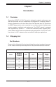
Chapter 1: Introduction Chapter 1 Introduction 1-1 Overview Supermicro's SC827 (2U Twin2) chassis is designed to optimize performance per Watt and per dollar with four independent hot-pluggable DP computing nodes efficiently organized into a 2U form factor. Each node provides three 3.5" hard drives for RAID 5 data protection, and is contained in a convenient module to facilitate easy system upgrades, installation and maintenance.
SC827 Chassis Manual 1-3 Contacting Supermicro Headquarters Address: Super Micro Computer, Inc. 980 Rock Ave. San Jose, CA 95131 U.S.A. Tel: +1 (408) 503-8000 Fax: +1 (408) 503-8008 Email: marketing@supermicro.com (General Information) support@supermicro.com (Technical Support) Web Site: www.supermicro.com Europe Address: Super Micro Computer B.V. Het Sterrenbeeld 28, 5215 ML 's-Hertogenbosch, The Netherlands Tel: +31 (0) 73-6400390 Fax: +31 (0) 73-6416525 Email: sales@supermicro.
Chapter 1: Introduction 1-4 Returning Merchandise for Service A receipt or copy of your invoice marked with the date of purchase is required before any warranty service will be rendered. You can obtain service by calling your vendor for a Returned Merchandise Authorization (RMA) number. When returning to the manufacturer, the RMA number should be prominently displayed on the outside of the shipping carton, and mailed prepaid or hand-carried.
SC827 Chassis Manual Notes 1-4
Chapter 2: System Safety Chapter 2 System Safety 2-1 Overview This chapter provides a quick setup checklist to get your chassis up and running. Following the steps in order given should enable you to have your chassis setup and operational within a minimal amount of time. This quick set up assumes that you are an experienced technician, famailiar with common concepts and terminology.
SC827 Chassis Manual • Do not work alone when working with high voltage components. • Power should always be disconnected from the system when removing or in- • • • • • • stalling main system components, such as the serverboard, memory modules and the DVD-ROM and floppy drives (not necessary for hot swappable drives). When disconnecting power, you should first power down the system with the operating system and then unplug the power cords from all the power supply modules in the system.
Chapter 2: System Safety 2-5 • • • • • 2-6 General Safety Precautions Keep the area around the chassis clean and free of clutter. Place the chassis top cover and any system components that have been removed away from the system or on a table so that they won’t accidentally be stepped on. While working on the system, do not wear loose clothing such as neckties and unbuttoned shirt sleeves, which can come into contact with electrical circuits or be pulled into a cooling fan.
SC827 Chassis Manual • • • • Handle a board by its edges only; do not touch its components, peripheral chips, memory modules or contacts. When handling chips or modules, avoid touching their pins. Put the serverboard and peripherals back into their antistatic bags when not in use. For grounding purposes, make sure your computer chassis provides excellent conductivity between the power supply, the case, the mounting fasteners and the serverboard.
Chapter 3: Chassis Components Chapter 3 Chassis Components 3-1 Overview This chapter describes the most common components included with your chassis. Some components listed may not be included or compatible with your particular chassis model. For more information, see the installation instructions detailed later in this manual. 3-2 Components Chassis The SC827 chassis includes twelve hot-swappable hard drive bays. For more information, visit our Web site at: http://www.supermicro.com.
SC827 Chassis Manual Power Supply Each SC827 chassis model includes a high-efficiency 80 Plus Gold Level power supply, rated at 1200 or 1400 Watts. In the unlikely event your power supply fails, replacement is simple and can be accomplished without tools. Air Shroud The SC827 chassis requires mylar air shrouds for each node to direct the airflow where cooling is needed. The air shroud will differ for different motherboards.
Chapter 4: System Interface Chapter 4 System Interface 4-1 Overview There are several LEDs on the control panel and on the drive carriers to keep you constantly informed of the overall status of the system. SC827 models include four control panels on the handles of the chassis which control each of the systems. This chapter explains the meanings of all LED indicators and the appropriate response you may need to take.
SC827 Chassis Manual 4-2 • • 4-3 Control Panel Buttons Power: The main power button on each of the four control panels is used to apply or remove power from the power supply to each of the four systems in the chassis. Turning off system power with this button removes the main power, but keeps standby power supplied to the system. Therefore, you must unplug system before servicing. The poer button has a built-in LED which will turn green when the power is on.
Chapter 4: System Interface as long as the temperature is too high or a fan does not function properly. • 4-4 NIC: Indicates network activity on either LAN1 or LAN2 when flashing . Drive Carrier LEDs The SC827 chassis uses SAS/SATA drives. SAS/SATA Drives Each SAS/SATA drive carrier has two LEDs. • • Blue: Each Serial ATA drive carrier has a blue LED. When illuminated, this blue LED (on the front of the SATA drive carrier) indicates drive activity.
SC827 Chassis Manual Notes 4-4
Chapter 5: Chassis Setup and Maintenance Chapter 5 Chassis Setup and Maintenance 5-1 Overview This chapter covers the steps required to install components and perform maintenance on the chassis. The only tool you will need to install components and perform maintenance is a Phillips screwdriver.
SC827 Chassis Manual 5-2 Chassis Cover 1 Remove two screws 2 13 Check Ventilation Openings 14 Figure 5-1: Removing the Chassis Cover Before operating the SC827 chassis for the first time, it is important to remove the protective film covering the top of the chassis, in order to allow for proper ventilation and cooling. Removing the Chassis Cover and Protective Film 1. Remove the two screws which secure the top cover onto the chassis as shown above. 2. Lift the top cover up and off the chassis. 3.
Chapter 5: Chassis Setup and Maintenance 5-3 Installing and Removing Hard Drives The SC827 chassis contains four individual motherboards in separate node drawers. Each motherboard node controls a set of three hard drives. Note that if a motherboard node drawer is pulled out of the chassis, the hard drives associated with that node will power down as well.
SC827 Chassis Manual 2 1 Figure 5-3: Removing a Hard Drive Tray Removing Hard Drive Trays from the Chassis 1. Press the release button on the drive tray. This extends the drive bay handle. 2. Use the handle to pull the drive out of the chassis.
Chapter 5: Chassis Setup and Maintenance Dummy Drive Drive Tray Figure 5-4: Chassis Drive Tray The drives are mounted in drive trays to simplify their installation and removal from the chassis. These trays also help promote proper airflow for the drive bays. ! Warning: Except for short periods of time while swapping hard drives, do not operate the server with the hard drives bays empty. 1 1 Figure 5-5: Removing Dummy Drive from Tray Installing a Drive into the Hard Drive Tray 1.
SC827 Chassis Manual SAS or SATA Hard Drive 4 4 Drive Tray Figure 5-6: Removing Hard Drive 3. Install a new drive into the tray with the printed circuit board side facing down so that the mounting holes align with those in the carrier. 4. Secure the hard drive by tightening all six (6) screws. 5. Use the open handle to replace the drive tray into the chassis. Make sure the close the drive tray handle.
Chapter 5: Chassis Setup and Maintenance 5-4 Removing and Installing the Backplane The SC827 chassis backplane is located behind the hard drives and in front of the front system fans. Although backplane failure rarely occurs, in the event of a backplane failure, follow the instructions below. Removing the Backplane Removing the Backplane from the Chassis 1. Power down and unplug the system from any power source. 2. Remove the chassis cover. 3. Disconnect the cabling to the backplane. 4.
SC827 Chassis Manual 6. Loosen the three screws in the spring bar, located on the floor of the chassis, indicated by the arrows below. 16 Figure 5-8: Loosening the Spring Bar Screws in the Floor of the Chassis 17 Figure 5-9: Removing the Backplane from the Chassis 7. Gently ease the backplane up and out of the chassis at a slight angle.
Chapter 5: Chassis Setup and Maintenance Installing the Backplane Installing the Backplane into the Chassis 1. Ensure that all of the hard drive trays have been removed from the bays in the front of the chassis and that the spring bar has been loosened as directed in the previous section. 2. Secure the side mounting bracket to the backplane with the two screws provided. 3. Slide the backplane into the chassis at a slight angle, pushing it up against the side of the chassis. 4.
SC827 Chassis Manual 5-5 Installing the Motherboard I/O Shields Figure 5-11: I/O Shield Placement Compatible Motherboards Most Supermicro Twin series motherboards are compatible with the SC827 chassis. For the most up-to-date information on compatible motherboards and other parts, visit the Supermicro Web site at www.supermicro.com. Hot-swappable motherboards feature different adapter cards, depending upon the motherboard. Adapter cards are optional and are not included with the chassis.
Chapter 5: Chassis Setup and Maintenance Figure 5-12: Installing the Motherboard in the Motherboard Node Drawer Installing the Motherboard 1. Review the documentation that came with your motherboard. Become familiar with component placement, requirements, precautions, and cable connections. 2. Pull the motherboard node drawer out of the back of the chassis. 3. Remove the add-on card brackets: 3a. Remove screw securing the add-on card bracket to the back of the node drawer. 3b.
SC827 Chassis Manual 8. Connect the cables between the motherboard, backplane, chassis, front panel, and power supply, as needed. Also, fans may be temporarily removed to allow access to the backplane ports. 9. Replace the add-on card bracket and secure the bracket with a screw. 10. Repeat steps 3 - 5 for the remaining nodes.
Chapter 5: Chassis Setup and Maintenance 5-6 Installing and Replacing Adapter Cards Adapter cards provide hot-swappable functionality to the chassis. Motherboard Drawer Adapter Card Spacer Plate Five Screws Figure 5-13: Adapter Card Installation Removing the Adapter Card 1. Remove the motherboard drawer from the chassis. 2. Disconnect the wiring, connecting the adapter card to the motherboard if any is present. 3.
SC827 Chassis Manual Add-on Card/Expansion Slot Setup The SC827 chassis supports one low-profile expansion slot for each node, for a total of four slots in the chassis. To install a low-profile PCI card, follow the instructions below.
Chapter 5: Chassis Setup and Maintenance Figure 5-15: Installing the Riser Card Installing the Riser Card Installing the Riser Card 1. Disconnect the power supply and lay the chassis on a flat surface. 2. Pull the motherboard node drawer from the chassis. 3. Remove the add-on card bracket. 3a. Remove the screw securing the add-on bracket to the back of the drawer. 3b. Lift the bracket out of the motherboard node drawer. 4.
SC827 Chassis Manual PCI Slot Shield Add-on Card Riser Card Screw Riser Card Figure 5-16: Installing the Add-On Card Installing Add-on Cards 1. Disconnect the power supply, lay the chassis on a flat surface, and open the chassis cover. 2. Pull out the motherboard node drawer from the chassis. 3. Pull open the add-on card slot clip in the rear of the motherboard node drawer. 4. Remove the PCI slot shield. 5. Place the add-on card into the motherboard node drawer. 6.
Chapter 5: Chassis Setup and Maintenance 5-7 Installing the Air Shrouds Air Shrouds Air shrouds concentrate airflow to maximize fan efficiency. The SC827 chassis requires air shrouds for each motherboard node. Air shrouds vary depending upon the motherboard used. See the illustrations below. Installing an Air Shroud 1. Make sure that the motherboard adapter card (if any) and all components are properly installed in each motherboard node. 2. Place the first air shroud over the motherboard, as shown below.
SC827 Chassis Manual 5-8 Checking the Airflow Checking Airflow 1. Make sure there are no objects to obstruct airflow in and out of the server. In addition, if you are using a front bezel, make sure the bezel's filter is replaced periodically. 2. Do not operate the server without drives or drive trays in the drive bays. Use only recommended server parts. 3. Make sure no wires or foreign objects obstruct airflow through the chassis. Pull all excess cabling out of the airflow path or use shorter cables. 4.
Chapter 5: Chassis Setup and Maintenance 5-9 System Fans Four fans provide cooling for the chassis. These fans circulate air through the chassis as a means of lowering the chassis internal temperature. The SC827 system fans are easy to change modules. There is no need to uninstall any other parts inside the system when replacing fans, and no tools are required for installation.
SC827 Chassis Manual Figure 5-18: System Fan Placement Changing a System Fan 1. If necessary, open the chassis while the power is running to determine which fan has failed. (Never run the server for an extended period of time with the chassis cover open.) 2. Remove the failed fan's power cord from the backplane. 3. Lift the fan housing up and out of the chassis. 4. Push the fan up from the bottom and out of the top of the housing. 5.
Chapter 5: Chassis Setup and Maintenance 5-10 Power Supply Depending on your chassis model, the SC827 chassis will include a 1200W or 1400W power supply. This power supply is auto-switching capable. This enables it to automatically sense and operate at a 100v to 240v input voltage. An amber light will be illuminated on the power supply when the power is off. An illuminated green light indicates that the power supply is operating.
SC827 Chassis Manual Changing the Power Supply 1. Power down all four nodes and unplug the power cord. (Not necessary with redundant power supplies) 2. Unplug the AC power cord from the failed power supply. 3. Push the release tab (on the back of the power supply) as illustrated. 4. Pull the power supply out using the handle provided. 5. Push the new power supply module into the power bay until you hear a click. 6. Plug the AC power cord back into the module and power up the nodes.
Chapter 6: Rack Installation Chapter 6 Rack Installation 6-1 Overview This chapter provides a quick setup checklist to get your chassis up and running. Following these steps in the order given should enable you to have the system operational within a minimal amount of time. 6-2 Unpacking the System You should inspect the box which the chassis was shipped in and note if it was damaged in any way. If the chassis itself shows damage, you should file a damage claim with the carrier who delivered it.
SC827 Chassis Manual ! 6-4 • Warning! ! Warnings and Precautions Rack Precautions Ensure that the leveling jacks on the bottom of the rack are fully extended to the floor with the full weight of the rack resting on them. • In single rack installations, stabilizers should be attached to the rack. • In multiple rack installations, the racks should be coupled together. • • • • • • • Always make sure that the rack is stable before extending a component from the rack.
Chapter 6: Rack Installation • 6-5 Always keep the rack's front door and all panels and components on the servers closed when not servicing to maintain proper cooling. Rack Mounting Considerations Ambient Operating Temperature If installed in a closed or multi-unit rack assembly, the ambient operating temperature of the rack environment may be greater than the ambient temperature of the room.
SC827 Chassis Manual 6-6 Rack Mounting Instructions This section provides information on installing the chassis into a rack unit with the rails provided. There are a variety of rack units on the market, which may mean that the assembly procedure will differ slightly from the instructions provided. You should also refer to the installation instructions that came with the rack unit you are using. NOTE: This rail will fit a rack between 26.5" and 36.4" deep.
Chapter 6: Rack Installation Locking Tabs Each inner rail has a locking tab. This tab locks the chassis into place when installed and pushed fully into the rack. These tabs also lock the chassis in place when fully extended from the rack. This prevents the server from coming completely out of the rack when when the chassis is pulled out for servicing. Releasing the Inner Rail Releasing Inner Rail from the Outer Rails 1. Identify the left and right outer rail assemblies as described on page 5-4. 2.
SC827 Chassis Manual Inner Rails 14 2 14 3 Figure 6-3: Installing the Inner Rails Figure 6-4: Inner Rails Installed on the Chassis (The chassis above are an example only. Actual chassis may differ slightly) Installing The Inner Rails on the Chassis Installing the Inner Rails 1. Confirm that the left and right inner rails have been correctly identified. 2. Place the inner rail firmly against the side of the chassis, aligning the hooks on the side of the chassis with the holes in the inner rail. 3.
Chapter 6: Rack Installation 1 L-min=676.00(26.61")(outer rail) 12 14 21D01 13 Figure 6-5: Extending and Releasing the Outer Rails Installing the Outer Rails on the Rack Installing the Outer Rails 1. Press upward on the locking tab at the rear end of the middle rail. 2. Push the middle rail back into the outer rail. 3. Hang the hooks of the front of the outer rail onto the slots on the front of the rack. If necessary, use screws to secure the outer rails to the rack, as illustrated above. 4.
SC827 Chassis Manual Ball-Bearing Shuttle Figure 6-6: Installing into a Rack Standard Chassis Installation Installing the Chassis into a Rack 1. Confirm that the inner rails are properly installed on the chassis. 2. Confirm that the outer rails are correctly installed on the rack. 3. Pull the middle rail out from the front of the outer rail and make sure that the ball-bearing shuttle is at the front locking position of the middle rail. 4. Align the chassis inner rails with the front of the middle rails.
Chapter 6: Rack Installation Optional Quick Installation Method The following quick installation method may be used to install the chassis onto a rack. Installing the Chassis into a Rack 1. Install the whole rail assembly onto the rack as described on page X-7. 2. Release the inner rail without retracting the middle rail. 3. Install the inner rails on the chassis as previously described on page X-6. 4. Install the chassis onto the middle rail as described in the previous section.
SC827 Chassis Manual Notes 6-10
Appendix A: Cables, Screws and Other Accessories Appendix A Cables, Screws, and other Accessories A-1 Overview This appendix lists optional parts which need to be ordered when the customer is assembling their own chassis system. It only includes the most commonly used components and configurations. For more compatible cables, refer to the manufacturer of the motherboard you are using and our Web site at: www.supermicro.com.
SC827 Chassis Manual A-5 Chassis Screws The chassis and accessory box includes all of the screws needed to setup your chassis. This section includes descriptions of the most common screws used. Your chassis may not require all of the parts listed. M/B HARD DRIVE Flat head 6-32 x 5 mm [0.197] Pan head 6-32 x 5 mm [0.197] DVD-ROM, CD-ROM, and FLOPPY DRIVE Pan head 6-32 x 5 mm [0.197] Flat head 6-32 x 5 mm [0.197] Round head 3 x 5 mm [0.197] Round head 2.6 x 5 mm [0.
Appendix B: Power Supply Specifications Appendix B SC827 Power Supply Specifications This appendix lists power supply specifications for your chassis system. SC827H-R1200B, SC827T-R1200B 1200W MFR Part # Rated AC Voltage PWS-1K21P-1R 100 - 140V, 50 - 60HZ, 8 - 11.5 Amp 180 - 240V, 50 - 60Hz, 5.5 - 8 Amp 1000W, 83 Amp @ 100-140V DC Output +12V 1200W, 100 Amp @ 180-240V 5Vsb: 4A +5V: 30 Amp DC Output +3.3V: 24 Amp with PDB -12V: 0.
SC827 Chassis Manual Notes B-2
Appendix C: SAS-827T Backplane Specificiations Appendix C SAS-827T Safety Guidelines To avoid personal injury and property damage, carefully follow all the safety steps listed below when accessing your system or handling the components. C-1 ESD Safety Guidelines Electrostatic Discharge (ESD) can damage electronic components. To prevent damage to your system, it is important to handle it very carefully. The following measures are generally sufficient to protect your equipment from ESD.
SC827 Chassis Manual C-3 An Important Note to Users • All images and layouts shown in this user's guide are based upon the latest PCB Revision available at the time of publishing. The card you have received may or may not look exactly the same as the graphics shown in this manual. C-4 Introduction to the SAS-827T Backplane The SAS-827T backplane has been designed to utilize the most up-to-date technology available, providing your system with reliable, high-quality performance.
Appendix C: SAS-827T Backplane Specificiations Connector, Jumper and Pin Definitions C-5 Front Connectors and Jumpers JP57 FAN4 1 F16 BAR CODE FAN3 BZ1 7 J7 C63 + R81 JP26: P10:GND P9:ACT#C1 P8:ACT#C0 P7:ACT#B2 P6:ACT#B1 C75 #A2 + JP18 R297 BUZZER RESET 1 JP18 OPEN:BUZZER DISABLE 1-2:BUZZER ENABLE 2-3:TEST P4:ACT#B0 P3:ACT#A2 P2:ACT#A1 P1:ACT#A0 3 U1 C29 D61 D56 7 R76 C18 R80 J6 C32 F1 F2 C57 C14 C35 C34 F6 F5 F4 4 + MB-B (PWR) JP13 1 C84 JP10 #A1 F3 C33 C21 C2
SC827 Chassis Manual JP30 FAN4 R81 JP18 OPEN:BUZZER DISABLE 1-2:BUZZER ENABLE 2-3:TEST 3 U1 D56 7 J6 C84 JP18 R297 BUZZER RESET 1 1 JP58 4 C32 213 C75 F1 MB-B (PWR) BZ1 7 #A2 F2 C57 C14 JP13 4 FAN1 JP54 R76 C18 R80 4 + JP59 C29 C35 MB-B (FAN) C34 1 #B1 1 C266 24 1 D57 J7 C63 + R77 C25 D61 JP10 #A1 F3 C33 4 7 C23 C21 #B0 22 D55 1 MB-A (FAN) MB-A (PWR) 4 7 J5 D60 R75 R79 C17 J8 SAS SAS SAS SAS SAS SAS SAS + F6 25 1 JF1-AB JF5 #A0 TOLERAN
Appendix C: SAS-827T Backplane Specificiations 5. - 8. Chassis Fan Connectors These connectors, designated JP54, JP55, JP56 and JP57 supply power to the chassis. cooling fans. 9. - 12. Fan Connector Y-Cable (Optional feature, sold separately) A Y-cable is used to connect the fan connector from the backplane to the motherboard's fan connectors. These fan connectors, are designated JP58, JP59, JP60 and JP65. Only connect a Y-cable into these four connectors.
SC827 Chassis Manual 13. Backplane Main Power Connectors The 4-pin connector, designated JP48 provides power to the backplane. See the table on the right for pin definitions. Backplane Main Power 4-Pin Connector (JP48) Pin# 1 2 and 3 4 14. - 15. Backplane to Front Panel Headers These connectors are designated JF5 and JF6. They connect the backplane to the front LED panels on the chassis. JF5 connects to the LED display panel for motherboards A and B.
Appendix C: SAS-827T Backplane Specificiations 22. - 33. SAS Ports The SAS-827T backplane is designed with four separate sectors, which support from one to four motherboards indepentdently of each other. The SAS ports are used to connect the SAS drive cables. The 12 ports are designated A0, A1, A2, B0, B1, B2, C0, C1, C2 and D0, D1, D2. Each port is also compatible with SATA drives. Use the table below to determine the SAS port to motherboard configuration that is appropriate for your system.
SC827 Chassis Manual C-7 Front Jumper Locations and Pin Definitions JP30 JP30 FAN4 To P/S JP48 3 JF2 C 19 A J7 C63 + R81 C29 7 R76 C18 R80 J6 C32 F1 F2 C57 C14 C35 C34 JP18 R297 BUZZER RESET 1 1 C84 JP58 4 JP10 #A1 3 JP18 F3 C33 4 1 MB-A (FAN) D55 MB-A (PWR) 4 7 J5 D60 R75 R79 C17 TOLERANCES DECIMAL ANGLE X .1 30 XX .03 MACH FINISH XXX.010 MB-B (PWR) J8 JF1-A C20 REV: 1.
Appendix C: SAS-827T Backplane Specificiations Front LED Indicators FAN4 D1 JP30 JP56 To P/S JP48 3 1 4 1 FAN3 JF2 C 19 A J7 C63 + R81 C29 7 R76 C18 R80 J6 C32 F1 F2 C57 C14 C35 1 C84 JP58 4 JP10 #A1 F3 C33 4 1 MB-A (FAN) C21 D55 MB-A (PWR) 4 7 J5 D60 R75 R79 C17 TOLERANCES DECIMAL ANGLE X .1 30 XX .03 MACH FINISH XXX.010 MB-B (PWR) J8 C20 REV: 1.
SC827 Chassis Manual C-8 Rear Connectors and LED Indicators SAS #A0 SAS/SATA A0 SAS #C0 SAS/SATA C0 SAS #B2 SAS/SATA B2 SAS #D2 SAS/SATA D2 SAS #B1 SAS/SATA B1 SAS #D1 SAS/SATA D1 SAS #B0 SAS/SATA B0 SAS #D0 SAS/SATA D0 SAS #A0 D12 SAS #A1 D13 SAS #A2 D14 SAS #B0 D15 SAS #B1 D18 SAS #B2 D21 SAS #C0 D22 SAS #C1 D24 SAS #C2 D25 SAS #D0 D26 SAS #D1 D27 SAS #D2 D28 C-10 C A SAS/SATA C1 13159 AC,ESOJ NAS A SAS/SATA C2 SAS #C1 Hard Drive Activity D26 D32 R175 R18
Appendix D: SAS-827B Backplane Specifications Appendix D SAS-827B Backplane Specifications To avoid personal injury and property damage, carefully follow all the safety steps listed below when accessing your system or handling the components. D-1 ESD Safety Guidelines Electrostatic Discharge (ESD) can damage electronic components. To prevent damage to your system, it is important to handle it very carefully. The following measures are generally sufficient to protect your equipment from ESD.
SC827 Chassis Manual D-3 An Important Note to Users • All images and layouts shown in this user's guide are based upon the latest PCB Revision available at the time of publishing. The card you have received may or may not look exactly the same as the graphics shown in this manual. D-4 Introduction to the SAS-827B Backplane The SAS-827B backplane has been designed to utilize the most up-to-date technology available, providing your system with reliable, high-quality performance.
Appendix D: SAS-827B Backplane Specifications Jumpers and Pin Definitions D-5 Front Connectors 12 1 16 FAN3 F27 F28 F29 F30 54 51 50 + Figure D-1: Front Connectors JPW2 47 18 MB-A 4 5 23 50 R204 R203 51 1 R222 8 24 13 1 11 1 C21 D55 JF1 C17 C24 C64 C26 D60 R215 R214 R206 R53 47 54 D58 JF5-AB 1 2 C49 23 24 C171 C170 C157 C155 C156 C124 D63 13 1 45 46 1 C84 + R224 50 D56 C14 C57 C80 + C44 51 D61 R49 C78 C77 C210 F17 TO PS 1 D66 1 4 JF5 D
SC827 Chassis Manual 1. - 3. Motherboard Power Connectors These connectors, designated JPW1, JPW2, and JPW3 supply power the four motherboard nodes in the chassis. 4. - 7. Chassis Fan Connectors These connectors, designated JP54, JP55, JP56 and JP57 supply power to the chassis. cooling fans.
Appendix D: SAS-827B Backplane Specifications 13. - 14. Backplane to Front Panel Headers These connectors are designated JF5 and JF6. They connect the backplane to the front LED panels on the chassis. JF5 connects to the LED display panel for motherboards A and B. JF6 connects to the LED display panel for motherboards C and D.
SC827 Chassis Manual D-6 Front Jumpers and Pin Definitions D56 R215 R214 R206 D62 C84 1 2 45 46 1 JF5-AB R222 + 50 51 JF5 D61 R49 C44 47 R223 JP36 JP35 C14 C57 C78 C77 C80 C210 F17 TO PS 1 4 C18 D59 C4 JPI2C1 54 C19 + C29 1 C46 C43 5 F31 F32 F33 F34 5 C85 23 C58 24 + MB-B R216 JF2 1 1 2 45 46 R217 R142 1 C15 CR13 C79 MB-A + JF1 C49 8 5 F27 F28 F29 F30 54 47 D60 23 C17 C24 D58 D55 1 13 C124 D63 C64 C26 1 24 R53 D66 MB-C 47 54 C
Appendix D: SAS-827B Backplane Specifications D-7 LED Indicators JF5 D56 + D62 + C44 JF5-AB C84 R215 R214 R206 TO PS 1 2 45 46 1 C14 C57 C78 C77 C80 C210 F17 JPI2C1 50 R223 D61 R49 R222 MB-A C49 + JF1 JF3 8 5 F27 F28 F29 F30 51 50 R204 R203 51 50 13 1 C171 C170 54 D55 47 D60 R224 C157 C155 C156 C124 D58 23 C17 C24 C64 C26 47 54 C126 C123 D63 24 R53 23 24 MB-C D59 C4 C18 C46 C43 1 4 C29 1 DEBUG C79 F36 1 2 45 46 J21 F31 F32 F33 F
SC827 Chassis Manual D-8 Rear Connectors and LED Indicators SAS/SATA A2 SAS #C2 SAS/SATA C2 SAS #A1 SAS/SATA A1 SAS #C1 SAS/SATA C1 SAS #A0 SAS/SATA A0 SAS #C0 SAS/SATA C0 SAS #B2 SAS/SATA B2 SAS #D2 SAS/SATA D2 SAS #B1 SAS/SATA B1 SAS #D1 SAS/SATA D1 SAS #B0 SAS/SATA B0 SAS #D0 SAS/SATA D0 Rear LED Indicators Rear LED Hard Drive Activity SAS #A0 D12 SAS #A1 D13 SAS #A2 D14 SAS #B0 D15 SAS #B1 D18 SAS #B2 D21 SAS #C0 D22 SAS #C1 D24 SAS #C2 D25 SAS #D0 D26 SAS
Appendix D: SAS-827B Backplane Specifications SAS Ports The SAS-827B backplane is designed with four separate sectors, which support from one to four motherboards indepentdently of each other. The SAS ports are used to connect the SAS drive cables. The 12 ports are designated A0, A1, A2, B0, B1, B2, C0, C1, C2 and D0, D1, D2. Each port is also compatible with SATA drives. Use the table below to determine the SAS port to motherboard configuration that is appropriate for your system.
SC827 Chassis Manual Disclaimer (cont.) The products sold by Supermicro are not intended for and will not be used in life support systems, medical equipment, nuclear facilities or systems, aircraft, aircraft devices, aircraft/emergency communication devices or other critical systems whose failure to perform be reasonably expected to result in significant injury or loss of life or catastrophic property damage.