
User`s manual


C-5
Safety Information and Technical Specifications
JP66
JP68
JP75
BZ1
D53 D54
D36
JP18
JP93
JP35
JP50
JP83
JP86
JP87
JP88
JP89
JP101
JP45
JP91
JP90
JP85
JP84
JP74
JP67
JP65
JP102
JP46
JP13
JP10
JP37
JP95
JP52
JP78
U2
J7
J6 J5
J8
J24
J23J25
J16 J14
J12
J10
J22
JP26
JP47
JP82
C
A
C A
1
GNDGND +12V
+5V
GNDGND
+12V
+5V
GNDGND
+12V
+5V
BAR CODE
ACT4
ACT11
ACT10
ACT9
ACT8
ACT3
ACT2
ACT1
ACT7
ACT6
ACT5
ACT0
9072RST
ALARM#1
ALARM#2
ACT_IN#8-11
ACT_IN#0-7
UPGRADE#2
JTAG#2
#0
#1
#2
#3
#4
#5
#7
#6
#11
#10
#9
#8
SIDEBAND#3
I2C#3
SIDEBAND#2
I2C#2
I2C#1
SIDEBAND#1
BUZZERRESET
REV 1.00
SAS826TQ
9071RST
JP89
JP50
JP65
JP67JP74
JP83
JP87
JP88
JP86
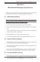
C-6 Front Jumper Locations and Pin Definitions
Explanation of Jumpers
To modify the operation of the backplane,
jumpers can be used to choose between
optional settings. Jumpers create shorts
between two pins to change the function
of the connector. Pin 1 is identified with
a square solder pad on the printed circuit
board. Note: On two pin jumpers, "Closed"
means the jumper is on and "Open" means
the jumper is off the pins.
Connector
Pins
Jumper
Setting
3 2 1
3 2 1
Jumper Settings
Jumper Jumper Settings Note
JP35
Open: Default
Closed: Reset
9072 Chip Reset #1
JP50
Open: Default
Closed: Reset
9071 Chip Reset #2
JP66
JP68
JP75
BZ1
D53 D54
D36
JP18
JP93
JP35
JP50
JP83
JP86
JP87
JP88
JP89
JP101
JP45
JP91
JP90
JP85
JP84
JP74
JP67
JP65
JP102
JP46
JP13
JP10
JP37
JP95
JP52
JP78
U2
J7
J6 J5
J8
J24
J23J25
J16 J14
J12
J10
J22
JP26
JP47
JP82
C
A
C A
1
GNDGND +12V
+5V
GNDGND
+12V
+5V
GNDGND
+12V
+5V
BAR CODE
ACT4
ACT11
ACT10
ACT9
ACT8
ACT3
ACT2
ACT1
ACT7
ACT6
ACT5
ACT0
9072 RST
ALARM#1
ALARM#2
ACT_IN#8-11
ACT_IN#0-7
UPGRADE#2
JTAG#2
#0
#1
#2
#3
#4
#5
#7
#6
#11
#10
#9
#8
SIDEBAND#3
I2C#3
SIDEBAND#2
I2C#2
I2C#1
SIDEBAND#1
BUZZER RESET
REV 1.00
SAS826TQ
9071 RST
JP91
JP102
JP85 JP84
JP101
JP35
JP93
JP90