SUPER ® SC825 CHASSIS Series SC825TQ-R740WB SC825TQ-R740UB SC825TQ-R720LPB SC825TQ-R740LPB SC825TQ-710LP(V)(B) SC825TQ-R720UB SC825TQ-R700LP(V)(B) SC825TQ-R700U(V)(B) SC825TQ-600LPB SC825TQ-563UB SC825TQ-563LPB SC825TQ-560LP(V)(B) SC825TQ-560U(V)(B) USER’S MANUAL 1.
SC825 Chassis Manual The information in this User’s Manual has been carefully reviewed and is believed to be accurate. The vendor assumes no responsibility for any inaccuracies that may be contained in this document, makes no commitment to update or to keep current the information in this manual, or to notify any person or organization of the updates. Please Note: For the most up-to-date version of this manual, please see our web site at www.supermicro.com. Super Micro Computer, Inc.
Preface Preface About This Manual This manual is written for professional system integrators and PC technicians. It provides information for the installation and use of the SC825 2U chassis. Installation and maintenance should be performed by experienced technicians only. Supermicro’s SC825 2U chassis features a unique and highly optimized design.
SC825 Chassis Manual Manual Organization Chapter 1 Introduction The first chapter provides a checklist of the main components included with this chassis and describes the main features of the SC825 chassis. This chapter also includes contact information. Chapter 2 System Safety This chapter lists warnings, precautions, and system safety.
Preface Appendices This section lists compatible cables, power supply specifications, and compatible backplanes. Not all compatible backplanes may be listed. Refer to our Web site for the latest compatible backplane information.
SC825 Chassis Manual Table of Contents Chapter 1 Introduction 1-1 Overview.......................................................................................................... 1-1 1-2 Shipping List..................................................................................................... 1-1 1-3 Chassis Features............................................................................................. 1-2 CPU.............................................................................
Preface Chapter 5 Chassis Setup and Maintenance 5-1 Overview.......................................................................................................... 5-1 5-2 Installation and General Maintnenance........................................................... 5-1 Installation........................................................................................................ 5-1 5-3 Removing the Chassis Cover..........................................................................
SC825 Chassis Manual Appendix A SC825 Chassis Cables Appendix B SC825 Power Supply Specifications Appendix C SAS-825TQ Backplane Specifications viii
Chapter 1: Introduction Chapter 1 Introduction 1-1 Overview Supermicro’s SC825 2U chassis features a unique and highly-optimized design. The chassis is equipped with a high-efficiency power supply. 1-2 Shipping List For the latest shipping lists visit the Supermicro Web site at www.supermicro.
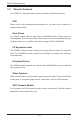
SC825 Chassis Manual 1-3 Chassis Features The SC825 2U, high-performance chassis includes the following features: CPU Please refer to the motherboard specifications on our Web site for updates on supported processors. Hard Drives The SC825 chassis features eight slots for SAS/SATA drives. These drives are hot-swappable. Once set up correctly, these drives can be removed without powering down the server. In addition, these drives support SES2 (SAS/SATA).
Chapter 1: Introduction Contacting Supermicro Headquarters Address: Super Micro Computer, Inc. 980 Rock Ave. San Jose, CA 95131 U.S.A. Tel: +1 (408) 503-8000 Fax: +1 (408) 503-8008 Email: marketing@supermicro.com (General Information) support@supermicro.com (Technical Support) Web Site: www.supermicro.com Europe Address: Super Micro Computer B.V. Het Sterrenbeeld 28, 5215 ML 's-Hertogenbosch, The Netherlands Tel: +31 (0) 73-6400390 Fax: +31 (0) 73-6416525 Email: sales@supermicro.
SC825 Chassis Manual 1-5 Returning Merchandise for Service A receipt or copy of your invoice marked with the date of purchase is required before any warranty service will be rendered. You can obtain service by calling your vendor for a Returned Merchandise Authorization (RMA) number. When returning to the manufacturer, the RMA number should be prominently displayed on the outside of the shipping carton, and mailed prepaid or hand-carried.
Chapter 2: System Safety Chapter 2 System Safety 2-1 Overview This chapter provides a quick setup to get your chassis up and running. Following the steps in order given should enable you to have your chassis set up and operational within a minimal amount of time. This quick setup assumes that you are an experienced technician, familiar with common concepts and terminology. 2-2 Warnings and Precautions You should inspect the box the chassis was shipped in and note if it was damaged in any way.
SC825 Chassis Manual 2-4 Electrical Safety Precautions Basic electrical safety precautions should be followed to protect yourself from harm and the SC825 from damage: • • • • • • • • • Be aware of the locations of the power on/off switch on the chassis as well as the room’s emergency power-off switch, disconnection switch or electrical outlet. If an electrical accident occurs, you can then quickly remove power from the system. Do not work alone when working with high voltage components.
Chapter 2: System Safety not discard a used battery in the garbage or a public landfill. Please comply with the regulations set up by your local hazardous waste management agency to dispose of your used battery properly. • 2-5 • • • • • 2-6 DVD-ROM laser: CAUTION - this server may have come equipped with a DVD-ROM drive. To prevent direct exposure to the laser beam and hazardous radiation exposure, do not open the enclosure or use the unit in any unconventional way.
SC825 Chassis Manual • • • • • • • Keep all components and printed circuit boards (PCBs) in their antistatic bags until ready for use. Touch a grounded metal object before removing any board from its antistatic bag. Do not let components or PCBs come into contact with your clothing, which may retain a charge even if you are wearing a wrist strap. Handle a board by its edges only; do not touch its components, peripheral chips, memory modules or contacts.
Chapter 3: Chassis Components Chapter 3 Chassis Components 3-1 Overview This chapter describes the most common components included with your chassis. Some components listed may not be included or may not be compatible with your particular chassis model. For more information, see the installation instructions detailed later in this manual. 3-2 Components Chassis The SC825 chassis includes eight hard drive bays. Hard drives must be purchased separately.
SC825 Chassis Manual Power Supply Each SC825 chassis model includes a high-efficiency power supply rated at 560W (single), 563W (single), 600W (single), 700W (redundant), 710W (single), 720W (redundant) or 740W (Redundant). Air Shroud Air shrouds are shields, usually plastic, which conduct the airflow directly to where it is needed. Always use the air shroud included with your chassis. 3-3 Where to get Replacement Components Although not frequently, you may need replacement parts for your system.
Chapter 4: System Interface Chapter 4 System Interface 4-1 Overview There are LEDs on the control panel and the drive carriers to keep you constantly informed of the overall status of the system, as well as the activity and health of specific components. Most SC825 models have two buttons on the chassis control panel: a reset button and an on/off switch. This chapter explains the meanings of all LED indicators and the appropriate response you may need to take.
SC825 Chassis Manual 4-2 Control Panel Buttons There are two push-buttons located on the front of the chassis. These are (in order from left to right) a reset button and a power on/off button. Reset: The reset button is used to reboot the system. Power: The main power switch is used to apply or remove power from the power supply to the server system. Turning off system power with this button removes the main power but keeps standby power supplied to the system.
Chapter 4: System Interface Informational LED Status Description Continuously on and red An overheat condition has occured. (This may be caused by cable congestion.) Blinking red (1Hz) Fan failure, check for an inoperative fan. Blinking red (0.25Hz) Power failure, check for a non-operational power supply. Solid blue Local UID has been activated. Use this function to locate the server in a rack mount environment. Blinking blue (300 mSEC) Remote UID is on.
SC825 Chassis Manual 4-4 Drive Carrier LEDs Your chassis uses SAS/SATA drives. SAS/SATA Drives Each SAS/SATA drive carrier has two LEDs. • • Green: Each Serial ATA drive carrier has a green LED. When illuminated, this green LED (on the front of the SATA drive carrier) indicates drive activity. A connection to the SATA backplane enables this LED to blink on and off when that particular drive is being accessed. Red: The red LED indicates a SAS/SATA drive failure.
Chapter 5: Chassis Setup and Maintenance Chapter 5 Chassis Setup and Maintenance 5-1 Overview This chapter covers the steps required to install components and perform maintenance on the chassis. The only tool you will need to install components and perform maintenance is a Phillips screwdriver. Print this page to use as a reference while setting up your chassis.
SC825 Chassis Manual 5-3 Removing the Chassis Cover 4 1 Remove Screw 2 3 2 1 Remove Screw Release Tab Figure 5-1: Removing the Chassis Cover Removing the Chassis Cover 1. Remove the two screws on each side of the cover, which secure the cover to the chassis. 2. Press the release tabs to remove the cover from the locked position. Press both tabs at the same time. 3. Once the top cover is released from the locked position, slide the cover toward the rear of the chassis. 4.
Chapter 5: Chassis Setup and Maintenance 5-4 Installing Hard Drives 2 1 Figure 5-2: Removing Hard Drive Removing Hard Drive Trays from the Chassis 1. Press the release button on the drive carrier. This extends the drive carrier handle. 2. Use the handle to pull the drive out of the chassis.
SC825 Chassis Manual Dummy Drive Drive Carrier Figure 5-3: Chassis Drive Carrier The drives are mounted in drive carriers to simplify their installation and removal from the chassis. These carriers also help promote proper airflow for the drive bays. ! Warning: Except for short periods of time (swapping hard drives), do not operate the server with the hard drives removed from the bays. 1 1 Figure 5-4: Removing Dummy Drive from Carrier Installing a Hard Drive to the Hard Drive Carrier 1.
Chapter 5: Chassis Setup and Maintenance SAS/SATA Hard Drive 4 Drive Carrier 4 Figure 5-5: Removing the Hard Drive 3. Install a new drive into the carrier with the printed circuit board side facing down so that the mounting holes align with those in the carrier. 4. Secure the hard drive by tightening all six screws. 5. Insert the drive carrier into the chassis bay, making sure that the drive carrier handle is completely closed.
SC825 Chassis Manual 5-5 Installing an Optional Peripheral or Fixed Hard Drive The SC825 chassis models include two open slots for an optional peripheral drive, and/or hard disk drive(s). To utilize these slots, the dummy drive and the slot cover must be removed. Removing and Installing the Dummy Drive, Peripheral Drive or Hard Disk Drive 1. Disconnect the chassis from any power source. 2. Press the release tab. 3.
Chapter 5: Chassis Setup and Maintenance 5-6 Slim DVD-ROM Installation or Replacement Installing or Replacing a Slim DVD-ROM Drive 1. Power down the system and if necessary, remove the server from the rack. 2. Remove the chassis cover. 3. Unplug the drives power and data cables from the motherboard and/or backplane. 4.
SC825 Chassis Manual 5-7 Installing the Motherboard I/O Shield Figure 5-9: I/O Shield Placement I/O Shield The I/O shield holds the motherboard ports in place. Install the I/O shield before you install the motherboard. Installing the I/O Shield Installing the I/O Shield 1. Review the documentation that came with your motherboard. Become familiar with component placement, requirements, and precautions. 2. Open the chassis cover. 3.
Chapter 5: Chassis Setup and Maintenance Permanent and Optional Standoffs Standoffs prevent short circuits by securing space between the motherboard and the chassis surface. The SC825 chassis includes permanent standoffs in locations used by most motherboards. These standoffs accept the rounded Phillips head screws included in the SC825 accessories packaging. Some motherboards require additional screws for heatsinks, general components and/or non-standard security.
SC825 Chassis Manual Installing the Motherboard 1. Review the documentation that came with your motherboard. Become familiar with component placement, requirements, precautions, and cable connections. 2. Open the chassis cover. 3. As required by your motherboard, install standoffs in any areas that do not have a permanent standoff. To do this: A. Place a hexagonal standoff screw through the bottom the chassis. B. Secure the screw with the hexagon nut (rounded side up). 4.
Chapter 5: Chassis Setup and Maintenance PCI Slot Setup The SC825 chassis includes PCI slots for expansion cards. The number of cards you can use depends upon your chassis model. SC825LP: Includes seven low-profile, full-length PCI slots. SC825U and SC825W: Includes four full-height, full-length and three low-profile PCI slots which support user-defined universal expansion cards. PCI Card Slots Figure 5-11: SC825 LP model Installing Expansion cards in SC825LP (Low-Profile) Chassis 1.
SC825 Chassis Manual PCI Slot Setup for SC825U (Universal Output) The SC825U chassis accepts a slightly smaller L-shaped motherboard to allow for a universal expansion card. This universal output card allows the systems to accept SAS, IB, Ethernet, and other types of connections. Installing a Riser Card in the SC825U Chassis: 1. Disconnect the power supply, lay the chassis on a flat surface, and open the chassis cover. 2. Plug the riser card into the designated riser card slot on the motherboard.
Chapter 5: Chassis Setup and Maintenance 5-8 Installing the Air Shroud Figure 5-12: Air Shroud for SC825LP Chassis Air shrouds concentrate airflow to maximize cooling efficiency. The SC825 chassis air shroud does not require screws for installation. Installing the Air Shroud 1. Confirm that your air shroud matches your chassis model. 2. Place the air shroud in the chassis. The air shroud fits behind the two fans closest to the power supply.
SC825 Chassis Manual Checking the Server's Air Flow Checking the Air Flow 1. Make sure there are no objects to obstruct airflow in and out of the server. In addition, if you are using a front bezel, make sure the bezel's filter is cleaned periodically. 2. Do not operate the server without drives or drive trays in the drive bays. Supermicro recommends enterprise level hard disk drives for the best reliability and performance. 3. Make sure no wires or foreign objects obstruct air flow through the chassis.
Chapter 5: Chassis Setup and Maintenance 5-9 System Fans Three heavy-duty fans provide the best cooling for the system. These fans circulate air through the chassis as a means of lowering the system's internal temperature. System fans are hot-swappable. This means that there is no need to power-down the system when replacing a system fan. Never run the system for an extended period of time without all of the required system fans in place and functioning properly.
SC825 Chassis Manual Figure 5-14: Placing the System Fan 5-16
Chapter 5: Chassis Setup and Maintenance 5-10 Power Supply Depending on your chassis model, the SC825 chassis has a 560W (single), 563W (single), 600W (single), 700W (redundant), 710W (single), 720W (redundant) or 740W (redundant) Watt power supply. Power supplies are auto-switching capable. This enables it to automatically sense and operate at a 100v to 240v input voltage. An amber light will be illuminated on the power supply when the power is off.
SC825 Chassis Manual Release Tab Figure 5-15: Removing the Power Supply Replacing the Power Supply 1. If your chassis includes a redundant power supply (at least two power modules), you can leave the server running and remove only one power supply. If your server has a single power supply, you must power-down the server and unplug the power cord before replacing the power supply. 2. Push the release tab (on the back of the power supply) as illustrated. 3.
Chapter 5: Chassis Setup and Maintenance Figure 5-16: Replacing the Power Distributor Replacing the Power Distributor Redundant server chassis require a power distributor. The power distributor provides failover and power supply redundancy. In the unlikely event you must replace the power distributor, do the following: 1. Power down the server and remove the plug from the wall socket or power strip. 2. Remove all cable connections to the power supply from the motherboard, backplane, and other components.
SC825 Chassis Manual Replacing or Installing the Front Port Panel Replace or Install the Front Port Panel 1. Power down the system and unplug the chassis power cord from the outlet. 2. Remove the chassis top cover. 3. Disconnect the power and data cables from the front port panel to other chassis components including the motherboard and backplane. 4. Remove the old port panel by depressing the release tab, then pulling the unit out of the chassis. 5.
Chapter 5: Chassis Setup and Maintenance 5-11 Optional Front Bezel The SC825 chassis supports an optional full-face locking front bezel for added security. The front bezel is not included with the SC825 chassis, but can be ordered seperately by visiting the Supermicro Web site at www.supermicro.com, clicking on the Where to Buy link and entering part number MCP-210-82503-0B.
SC825 Chassis Manual Notes 5-22
Chapter 6: Rack Installation Chapter 6 Rack Installation 6-1 Overview This chapter provides a quick setup to get your chassis up and running. Following these steps in the order given should enable you to have the system operational within a minimum amount of time. 6-2 Unpacking the System You should inspect the box the chassis was shipped in and note if it was damaged in any way. If the chassis itself shows damage you should file a damage claim with the carrier who delivered it.
SC825 Chassis Manual ! • Warnings and Precautions! Rack Precautions Ensure that the leveling jacks on the bottom of the rack are fully extended to the floor with the full weight of the rack resting on them. • In single rack installation, stabilizers should be attached to the rack. • In multiple rack installations, the racks should be coupled together. • • • • • • • • ! Always make sure the rack is stable before extending a component from the rack.
Chapter 6: Rack Installation Rack Mounting Considerations Ambient Operating Temperature If installed in a closed or multi-unit rack assembly, the ambient operating temperature of the rack environment may be greater than the ambient temperature of the room. Consideration should be given to installing the equipment in an environment compatible with the manufacturer’s maximum rated ambient temperature (Tmra).
SC825 Chassis Manual 6-4 Rack Mounting Instructions This section provides information on installing the SC825 chassis into a rack unit with the quick-release rails provided. There are a variety of rack units on the market, which may mean the assembly procedure will differ slightly. You should also refer to the installation instructions that came with the rack unit you are using. NOTE: This rail will fit a rack between 26.5" and 36.4" deep.
Chapter 6: Rack Installation 13 2 13 1 Figure 6-2: Installing the Inner Rail Extensions Installing the Inner Rail Extension The SC825 chassis includes a set of inner rails in two sections: inner rails and inner rail extensions. The inner rails are pre-attached to the chassis, and do not interfere with normal use of the chassis if you decide not to use a server rack. The inner rail extension is attached to the inner rail to mount the chassis in the rack. Installing the Inner Rails 1.
SC825 Chassis Manual 13 1 SCREW screw the handles the outer rails for secure purpose if necessary 12 Figure 6-3: Assembling the Outer Rails Outer Rack Rails Outer rails attach to the rack and hold the chassis in place. The outer rails for the SC825 chassis extend between 26.5 inches and 36.4 inches. Installing the Outer Rails to the Rack 1. Secure the back end of the outer rail to the rack, using the screws provided. 2.
2 F. Chapter 6: Rack Installation SCREW 1 Figure 6-4: Installing the Chassis into the Rack Installing the Chassis into a Rack 1. Extend the outer rails as illustrated above. 2. Align the inner rails of the chassis with the outer rails on the rack. 3. Slide the inner rails into the outer rails, keeping the pressure even on both sides. When the chassis has been pushed completely into the rack, it should click into the locked position. SCREW screw the handles 4.
SC825 Chassis Manual Notes 6-8
Appendix A: Chassis Cables Appendix A SC825 Chassis Cables A-1 Overview This appendix lists supported cables for your chassis system. It only includes the most commonly used components and configurations. For more compatible cables, refer to the manufacturer of the motherboard you are using and our Web site at: www.supermicro.com. A-2 Cables Included with SC825TQ Chassis The following chart contains the basic set of cables included with SC825TQ chassis models. Some models may include additional cables.
SC825 Chassis Manual A-5 Compatible Cables These cables are compatible with the SC825 Chassis. Alternate SAS/SATA Cables Some compatible motherboards have different connectors. If your motherboard has only one SAS connector that the SAS/SATA cables must share, use one of the following cables. These cables must be purchased separately. Cable Name: SAS Cable Quantity: 1 Part #: CBL-0175L Alt.
Appendix A: Chassis Cables Extending Power Supply Cables Although Supermicro chassis are designed to be efficient and cost-effective, some compatible motherboards have power connectors located in different areas. To use these motherboards you may have to extend the power cables to the mother boards. To do this, use the following chart as a guide. Power Cable Extenders Number of Pins Cable Part # Length 24-pin CBL-0042L 7.9” (20 cm) 20-pin CBL-0059L 7.9” (20 cm) 8-pin CBL-0062L 7.
SC825 Chassis Manual Notes A-4
Appendix B: Power Supply Specifications Appendix B SC825 Power Supply Specifications This appendix lists power supply specifications for your chassis system. SC825 Series 560W 563W 600W R700W (Redundant) MFR Part # PWS-561-1H20 PWS-563-1H20 PWS-605P-1H PWS-702AIR Rated AC Voltage 100 - 240V 50 - 60Hz 8.5 - 4 Amp 100-240 V 50-60 Hz 7.5 Amp max 100-240 V 50-60 Hz 7.5 Amp max 100 - 240V 60-50Hz 10 - 4 Amp 3 Amp 3 Amp 4 Amp 43.
SC825 Chassis Manual SC825 Series 710W DC-DC Power Supply R720W (Redundant) 740W MFR Part # PWS-711-1R PWS-721P-1R PWS-741P-1R Rated AC Voltage --- --- 100-240 V, 50-60 Hz 9-3.5 Amp AC Input --- 100-240 V, 50-60 Hz, 4-9 Amp --- DC Input Voltage Voltage Range = -36V to -75V (24A - 11A) Nominal Voltage = -48V --- --- DC Output --- 3 Amp @ +5V standby 59 Amp @ +12V 4 Amp @ +5V standby 61.7 Amp @ +12V +5V standby 4 Amp --- --- +12V 59 Amp --- --- +5V 30 Amp 45 Amp --- +3.
Chapter 1: Safety Guidelines Appendix C SAS-825TQ Backplane Specifications To avoid personal injury and property damage, carefully follow all the safety steps listed below when accessing your system or handling the components. C-1 ESD Safety Guidelines Electrostatic Discharge (ESD) can damage electronic components. To prevent damage to your system, it is important to handle it very carefully. The following measures are generally sufficient to protect your equipment from ESD.
SAS-825TQ Backplane User's Guide C-3 An Important Note to Users All images and layouts shown in this user's guide are based upon the latest PCB Revision available at the time of publishing. The card you have received may or may not look exactly the same as the graphics shown in this manual. C-4 Introduction to the SAS-825TQ Backplane The SAS-825TQ backplane has been designed to utilize the most up-to-date technology available, providing your system with reliable, high-quality performance.
Chapter 2: Safety Guidelines C-5 Front Connectors and SAS Ports +12V GND GND +5V +12V GND GND 15 16 18 14 13 12 10 1 +5V 1 ACT_IN SAS825TQ + + REV 2.0 ++ ++ ++ + + JP29:9072 RESET ++ 11 1 BAR CODE 48 1 2 #2 IC SIDEBAND #2 1 ++ 1 16 17 2 #1 IC 32 SIDEBAND #1 19 Figure C-1: Front Connectors Front Connectors SAS Ports 1. 4-pin power connector: JP13 12. SAS Port #0 2. 4-pin power connector: JP10 13. SAS Port #1 3. CD-ROM/floppy connector: JP18 14.
SAS-825TQ Backplane User's Guide C-6 Front Connector and Pin Definitions #1 and #2 Backplane Main Power Connectors Backplane Main Power 4-Pin Connector The 4-pin connectors, designated JP10, and JP13 provide power to the backplane. See the table on the right for pin definitions.
Chapter 2: Safety Guidelines #8 and #9 Sideband Headers Sideband Headers The sideband headers are designated JP51 and JP52. For SES-2 to work properly, you must connect an 8-pin sideband cable. See the table to the right for pin definitions. #10 MG9072 Chip The MG9072 is an enclosure management chip that supports the SES-2 controller and SES-2 protocols. #11 Upgrade Header The upgrade header is designated JP46 and is used for manufacturing purposes only.
SAS-825TQ Backplane User's Guide C-7 Front Jumper Locations and Pin Definitions JP43 ACT_IN GND GND +5V +12V GND GND JP36 1 #2 SIDEBAND #2 1 SAS825TQ REV 2.0 48 1 ++ ++ + + ++ + + JP29:9072 RESET JP29 JP50 JP38 ++ JP18 2 IC +5V BAR CODE 2 IC #1 ++ +12V JP37 JP33 JP34 JP41 JP40 Figure C-3: Front Jumpers 16 32 SIDEBAND #1 JP42 Explanation of Jumpers To modify the operation of the backplane, jumpers can be used to choose between optional settings.
Chapter 2: Safety Guidelines SGPIO and I2C Modes and Jumper Settings This backplane can utilize SGPIO or I2C. SGPIO is the default mode and can be used without making changes to your jumpers. The following information describes which jumper must be configured to use SGPIO mode.
SAS-825TQ Backplane User's Guide I2C Settings Jumper Jumper Setting Notes JP33 2-3 Controller ID #1 JP34 1-2 Backplane ID #1 1-2: ID#0 2-3: ID#1 JP36 2-3 Controller ID #2 JP37 2-3 Backplane ID #2 1-2: ID#0 2-3: ID#1 JP38 Closed (Jumper on the pins) I2C Reset #2 JP40 Open (Jumper off the pins) I2C Reset_SDOUT#1 JP41 Open (Jumper off the pins) I2C Reset_SDOUT#2 JP42 2-3 I2C Backplane ID_SDIN#1 JP43 2-3 I2C Backplane ID_SDIN#2 JP50 Closed (Jumper on the pins) I2C Reset #1 C-6
Chapter 2: Safety Guidelines SAS Port Connections in I2C and SGPIO Settings Use the following chart when connecting this backplane. If the SAS ports are connected out of order, it is not easy to identify drives using the LED function. SAS Port Connections in I2C and SGPIO Settings Port # I2C SGPIO #0-3 I2C #1 Sideband #1 #4-7 I2C #2 Sideband #2 Front LED Indicators ACT_IN +12V GND GND +5V +12V GND GND 2 #2 IC SIDEBAND #2 +5V 1 1 SAS825TQ + + REV 2.
SAS-825TQ Backplane User's Guide Rear Connector SAS Drive Number SAS #0 J1 SAS/SATA HDD #0 SAS #4 J9 SAS/SATA HDD #4 SAS #1 J2 SAS/SATA HDD #1 SAS #5 J11 SAS/SATA HDD #5 SAS #2 J3 SAS/SATA HDD #2 SAS #6 J13 SAS/SATA HDD #6 SAS #3 J4 SAS/SATA HDD #3 SAS #7 J15 SAS/SATA HDD #7 Rear LED Indicators Rear LED Hard Drive Activity Failure LED SAS #0 D12 D5 SAS #1 D13 D6 SAS #2 D14 D7 SAS #3 D15 D8 SAS #4 D18 D19 SAS #5 D21 D20 SAS #6 D22 D23 SAS #7 D25 D26 C-8 ACT7 FAI
Chapter 2: Safety Guidelines Notes C-9
SAS-825TQ Backplane User's Guide Disclaimer (cont.) The products sold by Supermicro are not intended for and will not be used in life support systems, medical equipment, nuclear facilities or systems, aircraft, aircraft devices, aircraft/emergency communication devices or other critical systems whose failure to perform be reasonably expected to result in significant injury or loss of life or catastrophic property damage.