SUPER (SC823T/SC823S) (SC823i) SC823 CHASSIS USER'S GUIDE 1.
SC823 Chassis User’s Guide The information in this User’s Guide has been carefully reviewed and is believed to be accurate. The vendor assumes no responsibility for any inaccuracies that may be contained in this document, makes no commitment to update or to keep current the information in this manual, or to notify any person or organization of the updates. Please Note: For the most up-to-date version of this manual, please see our web site at www.supermicro.com.
Chapter 1: Safety Information and Technical Specifications Table of Contents Chapter I: Safety Information and Technical Specifications .......... 1-4 1-1. Electrical Safety Guidelines ............................................................ 1-4 1-2. General Safety Guidelines ............................................................... 1-5 1-3. ESD Safety Guidelines ....................................................................... 1-6 1-4. Operation Safety Guidelines ..........................
SC823 Chassis User’s Guide Chapter 1-Safety Information and Technical Specifications 1-1 Electrical Safety Guidelines Warning: To avoid electrical shock, cords as follows: check the power Checking the Power Cords !Use the exact type of power cords as required. !Be sure to use power cord(s) that came with safety certifications. !The power cord(s) must be compliant with the AC voltage requirements in your region.
Chapter 1: Safety Information and Technical Specifications Use rubber mats specifically designed as electrical insulators when working with computer systems. The power supply or power cord must include a grounding plug and must be plugged into grounded outlets. Motherboard Battery: CAUTION -Make sure not to install the onboard battery upside down to avoid possible explosion. Make sure that the positive side should be facing up on the motherboard.
SC823 Chassis User’s Guide 1-3 ESD Safety Guidelines Electric Static Discharge (ESD) can damage electronic components. To prevent damage to your system board, it is important to handle it very carefully. The following measures are generally sufficient to protect your equipment from ESD. Use a grounded wrist strap designed to prevent static discharge. Keep all components and printed circuit boards (PCBs) in their antistatic bags until ready for use.
Chapter 1: Safety Information and Technical Specifications To avoid personal injury and property damage, please carefully follow all the safety steps listed below: Before accessing the chassis: 1. Turn off all peripheral devices connected to the SC823. 2. Press the power button to power off the system. 3. Unplug all power cords from the system or the wall outlets. 4. Disconnect all the cables and label the cables for easy identification. 5.
SC823 Chassis User’s Guide Before installing the chassis into a rack: 1. Make sure that the rack is securely anchored onto an unmovable surface or structure before installing the chassis into the rack. 2. Unplug the power cord(s) of the rack before installing the chassis into the rack. 3. Make sure that the system is adequately supported and that all the components are securely fastened to the chassis to prevent components from falling off from the chassis. 4.
Chapter 1: Safety Information and Technical Specifications 1-6 Packing List and the SC823 Specifications A. The SC823 Series chassis contains the following: ! ! ! ! One (1) 1.44" floppy drive One (1) slim CD-ROM drive (*For 823S-R500LP, 823S-R500RC, 823T-R500RC, 823i-R500RC only) One (1) 5.
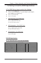
SC823 Chassis User’s Guide For the SC823-SCSI Models-(*823S-R500LP/-R500RC/-R550LP) Component SCA Drive Tray 8 cm Hot -Swap Chassis Fan 550W Power Supply 500W Power Supply 6-port SCSI Backplane SCSI Cable Floppy Drive CD ROM Rackmount Hardware SC823S-SCSI Part# CSE-PT17 (B) Fan-0070 PWS-0047 PWS-0049 CSE-SCA-822 CBL-033-U320 FPD-PNSC-02(01) CDM-TEAC-024(B) CSE-PT-25 Qty 6 4 1 2 1 1 1 1 1 Notes (*for 823S-550LP) (*for 823S-R500RC/R500LP) (*for Redundant Chassis) For the SC823-SATA Models-(*823T-R550LP
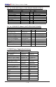
Chapter 1: Safety Information and Technical Specifications D. Serial ATA Back Panel (*SC823T only) D-1 Jumper Settings and Pin Definitions Jumpers JP18 JP25 JP26 D-2 Default Settings Open 1-2 Open Notes Buzzer Reset (*Note Below) Overheat Temperature at 500C Common Act In and Act#0-#5 In Jumper Locations JP25 JP18 S UPER R SATA822 REV 1.
SC823 Chassis User’s Guide E. SCSI Back Panel (*SC823S Only) E-1 Jumper Settings and Pin Definitions E-2 Jumper ! " $ " % & Locations 4-pin PWR Connectors SCSI Connector JP18 JP S UPER R SCA822S REV 1.
Chapter 2: Chassis Description and Installation Instructions Chapter 2: Chassis Description and Installation Instructions 2-1 Chassis Description A. Contents of the Accessory Kit: The following items are included in the Accessory Kit: 6FUHZV IRU 'ULYHV M/B Standoffs A M5 x 6-32 x 6.5L A. E B M5 x 6-32 x 7.7L B.
SC823 Chassis User’s Guide B. Chassis Front View and the Front Control Panel Chassis Front Panel The SC823T/SC823S Series B A C D Front Panel I/O Device Definitions (* for the SC823T/SC823S Series) A. SCA Drive Trays(6) C. 5.25" Drive Bay(1) B. Floppy Disk(1) D. CD ROM(1) (*Redundant Chassis only) The SC823i Series B A C Front Panel I/O Device Definitions (* for the SC823i Series) A. IDE Drive Trays(2) B. Floppy Disk(1) C. 5.25" Drive Bay(1) D.
Chapter 2: Chassis Description and Installation Instructions LED Panel L K J I F G H E LED and Button Definitions E. Power Button F. Reset Button I. LAN1 J. LAN2 K. Overheat L. System Alert/Power Failure (*for Redundant PS only) G. Power Indicator H.
SC823 Chassis User’s Guide C. Chassis Rear View and the Back Panel SC823 Chassis Rear View (*SC823T/823S/823i-LP Models) B A A1 C B C Back Panel Devices (*P/N: CSE-PT21) A. Power Supply A1. Redundant Power Supply B. Back Panel I/O Ports C. Low Profile Expansion Slots(7) SC823 Chassis Rear View (*SC823T/823i-RC Models) C B A A1 B Back Panel Devices (*P/N: CSE-PT22) A. Power Supply A1. Redundant Power Supply B. Back Panel I/O Ports C.
Chapter 2: Chassis Description and Installation Instructions *I/O Back Panel (*installed on the back panel-See Page 2-4) H D E F G *I/O Back Panel H USB 1 VGA USB 2 D F E LAN 1 G Back Panel I/O Port Definitions D. Keyboard & Mouse E. USB Ports F. COM/Video Ports G. LAN1 (& LAN2) H. Parallel Port (*Note: The actual I/O Configuration of your system might be different from the one shown above.
SC823 Chassis User’s Guide 2-2 Chassis Installation A. Important Safety Guidelines Stop This product shall only be accessed, assembled and serviced by technically qualified personnel or technicians. To avoid personal injury and property damage, please read all the information provided in Chapter 1, and carefully follow all the Safety Guidelines listed before accessing or servicing the SC823 or its components. For your convenience, some Safety Steps are also listed below.
Chapter 2: Chassis Description and Installation Instructions C. Removing the Top Cover of the SC823 Chassis Before installing any components, replacing chassis fans or accessing the motherboard, you will first need to remove the top cover. Procedures 1. Press the release tabs to release the cover from its locking position. 1 1 2 2 1 2 2. Once the top cover is released from its locking position, push the cover toward the rear side and slide it out from the chassis.
SC823 Chassis User’s Guide D1. Accessing the SCSI (or SATA) Drive Tray and Installing a Hard Disk(*For the SC823S/823T series) To install the SCA(SATA) drive into the chassis, you need to first remove the SCA(SATA) drive tray from the chassis. Procedures 1. Press the release tab located on the drive tray door to release the drive tray from its locking position as shown below. 2. Pull the drive tray door upward and then pull the drive tray out from the chassis.. 2a 1 2b 3.
Chapter 2: Chassis Description and Installation Instructions D2. Accessing the IDE Drive Tray and Installing a Hard Disk (*For the SC823i Series) To install the IDE drive into the chassis, first, you need to remove the top cover; then, you need to remove the IDE drive tray from the chassis. Procedures 1. Remove the screws from the top of the IDE drive as shown below. 2. Once the top cover and the screws are removed, press on the back side of the IDE drive tray and push it out from the chassis.. 1 2 3.
SC823 Chassis User’s Guide E. Accessing the Front Chassis Fans and Installing the Air Shroud Procedures: Accessing Chassis Fans 1. Press the release tab located on the left side of the front chassis fan (when facing the front side of the fan) to release it from its locking position as shown in the picture below. 2. Once the front chassis fan is loosened, you can pull it out. 1 2 Procedures: Installing the Air Shroud 1.
Chapter 2: Chassis Description and Installation Instructions F. Accessing the Redundant Power Supply (*For the 8S3SR550RC/R500LP, 823T-R500RC, 823i-R500RC) (Caution: Unplug the Power Cord before removing the Power Supply!!) Procedures 1. Locate the release tab on the left side of the power supply. 2. Push the release tab to the right to release the power supply from its locking position as shown below. 1 3 2 3.
SC823 Chassis User’s Guide G. Installing the Motherboard Be sure to disconnect the power supply before accessing or installing the motherboard into the chassis. To install the motherboard to the chassis, first, you will need to install the correct type of standoffs at the proper locations before installing the motherboard into the chassis. (Refer to Chapter 1 for Safety Guidelines.) Procedures 1. Lay the chassis on a flat surface.
Chapter 2: Chassis Description and Installation Instructions H. Installing Chassis Rails Please make sure that the chassis covers and chassis rails are installed on the chassis before you install the chassis into the rack. To avoid personal injury and property damage, please carefully follow all the safety steps listed below. Before installing the Chassis rails: 1. Enclose the chassis with chassis covers. 2. Unplug the AC power cord(s). 3. Remove all external devices and connectors.
SC823 Chassis User’s Guide 3. Locate the five rail hooks on each side of the chassis and the five corresponding holes on each of the inner rail. 4. Align the five holes on the rail against the corresponding hooks on the chassis. Once aligned, attach the inner rail to the chassis by pressing the holes into the corresponding hooks. 5. Once the rail is placed on the chassis, pull the rail forward until you hear the click. 6.
Chapter 2: Chassis Description and Installation Instructions I. Rack Installation After you have installed the inner rails on the chassis, you are ready to install the outer rails of rail assemblies to the rack. (* The rails are designed to fit in the racks with the depth of 28" to 33".) Procedures 1. In the package, locate a pair of front (-short) and rear (-long) brackets. Please note that the brackets are marked with Up/Front Arrows (-front) and Up/Rear arrows (-rear). 2.
SC823 Chassis User’s Guide 7. Slide the SC823 chassis into the rack until you hear the click. (The SC823 chassis may not slide into the rack smoothly or easily when installed the first time. However, some adjustment to the slide assemblies might be needed for easy installation.) 8. You will need to release the safety tabs on both sides of the chassis in order to completely remove the chassis out of the rack.