SUPER The SC818 Chassis Series User Guide Rev. 1.
SC818 Chassis User's Guide The information in this User’s Manual has been carefully reviewed and is believed to be accurate. The vendor assumes no responsibility for any inaccuracies that may be contained in this document, makes no commitment to update or to keep current the information in this manual, or to notify any person or organization of the updates. Please Note: For the most up-to-date version of this manual, please see our web site at www.supermicro.com.
Chapter 1: Introduction Table of Contents Chapter I: Introduction .................................................................1-4 A. Safety Guidelines ......................................................................................... 1-4 B. Packing Lists ................................................................................................ 1-6 C. SC818 Chassis Front Panel ........................................................................ 1-8 D. The SC818 Chassis Specifications...
SC818 Chassis User's Guide Chapter 1- Introduction A. Safety Guidelines A-1 Electricity Safety General Electrical Safety Guidelines ! • Use the exact type of power cords as required. • Be sure to use power cord(s) that came with safety certifications. • The power cord(s) must be compliant with the AC voltage requirements in your region. • Plug the Power cord(s) into a socket that is properly grounded before turning on the power.
Chapter 1: Introduction A-3. General Safety Guidelines ! • Warning!! Follow the guidelines below to avoid possible damage to the system or injury to yourself: To avoid injuries to your back, be sure to use your leg muscles, keep your back straight, and bend your knees, when lifting the system. • After removing the components or chassis covers from the system, place them on a table for safeguard.
SC818 Chassis User's Guide B. Packing Lists B-1.
Chapter 1: Introduction B-3.
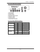
SC818 Chassis User's Guide C. The SC818 Chassis Front Panel Top View 6 3 2 5 7 4 1 C-1. Major Chassis Components 1. Front Control Panel (*See C-2 below) 2. Power Module 6. Chipset 3. Power Back Plane 7. DDR Memory Modules (8) 4. Fan Modules (6) 5. CPUs (4) Front View 3 5 2 4 1 4 4 C-2. Front Panel LED Indicators and IO Ports 1. Front Panel LED Indicators (*See C-3 below) 2. CD-ROM/DVD-ROM 3. Power Supply Module 4. Hard Disk Drives (3) 5.
Chapter 1: Introduction C-3. Front Panel LED Indicators 7 6 5 4 3 2 1 1. Power Button 2. Reset Button 3. Power-on LED 4. Hard Drive Activity LED 5. LAN Port1 LED 6. LAN Port2 LED 7. Overheat/Fan Fail LED C-4.
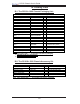
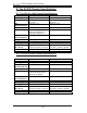
SC818 Chassis User's Guide D. The SC818 Chassis Specifications D-1. The SC818+-1000 Chassis Specifications Model Form Factor CPU Support SC818S+-1000 1U Rackmount AMD Quad Opteron Processors ATX 13” x 16” Max. Motherboard Size 1 Expansion Slots SCA or HD Bays Three 1”hot-swap Ultra 320/160 SCSI drive bays (SAF-TE Compliant) Optional Front Side USB Port &COM port Floppy/CD-ROM Optional/Yes 1000W cold-swap PS Power Supply Six 40mmx40mmx56mm Cooling System 17.2” x 1.7” x 27.
Chapter 1: Introduction E. The SC818 Chassis Power Supply Specifications Power Supply Spec SC818 Mfr. Model # Mfr. Part # Rated AC Input Voltage Rated Input Frequency Rated Input Current PWS-1K01-1R PWS-1K01-1R 100-240 VAC 50-60 Hz 15A (115V) 10A (230V) 1000W 4400 BTUs/Hr Rated Output Power Maximum rated BTU Nominal Output Voltage +12V 83A +5Vsb 4A Mfr. Model # Mfr. Part # +5V +3.3V -12V PDB-PT818-8824 PDB-PT818-8824 20A 20A 0.
SC818 Chassis User's Guide Notes 1-12
Chapter 2: Installation Procedures Chapter 2: Installation Procedures Section 1: Installing Components into the SC818 A. Removing the Top Cover from the Chassis Before installing any components, replacing chassis fans or accessing the motherboard, you will first need to remove the top cove from the chassis. Procedures 1. Using a Philips screw driver, remove two screws from the top cover as shown below. 2. Unlock and remove the thumb screw from the chassis. 3.
SC818 Chassis User's Guide B. Removing the Riser Card Bracket from the Chassis Before installing the motherboard, you will need to remove the riser card bracket from the chassis. Procedures 1. After the top cover is removed from the chassis, using a Philips screw driver to remove the two screws on the riser card bracket as shown below: 2. Remove the riser card bracket from the chassis.
Chapter 2: Installation Procedures C. Installing the Motherboard into the Chassis After you've removed the chassis cover and the riser card bracket from the chassis, you are ready to install the motherboard into the chassis. Procedures 1. Locate the mounting holes on the motherboard and the mounting holes on the chassis. 2. Align the mounting holes on the motherboard against the corresponding mounting holes on the chassis. Once aligned, place the motherboard on top of the chassis. 3.
SC818 Chassis User's Guide 4. Connect power cables to the power connectors on the motherboard as shown below. 5. Connect fan cables to the fan headers on the motherboard as shown in the picture below.
Chapter 2: Installation Procedures D. Installing the Chipset Air Shroud into the Chassis After the MB is securely installed into the chassis, you will need to install the chipset air shroud to prevent the chipset from overheat. Procedures 1. Align the chipset air shroud with the chipset. 2. Once aligned, secure the chipset air shroud into the chassis with a 6-32 x 13L screw as shown below. 3. Connect fan cables to the fan headers on the motherboard as shown below.
SC818 Chassis User's Guide E. Installing the CPU Air Shroud into the Chassis After you have installed the CPU and the CPU Heatsink into the chassis, you will need to install the CPU air shroud to prevent the processors from overheat. Procedures 1. Before installing the air shroud, make sure that the CPU, the heatsink and the memory modules are properly installed. 2. Align the CPU air shroud with the CPUs. 3. Once aligned, secure the CPU air shroud into the chassis with a 6-32 screw as shown below. 4.
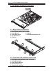
Chapter 2: Installation Procedures F. Accessing the Hard Disk Drive Tray and Installing a Hard Drive To install a hard disk drive into the chassis, you need to first remove the HDD tray from the chassis so that the HDD can be installed in. Procedures 1. Press the release tab to unlock the HDD tray. 2. Pull the HDD tray out from the chassis as shown below: 1 2 3. Remove the two screws that attach to the both sides of the dummy HDD, and take out the dummy HDD as shown below: 3b 3a 4.
SC818 Chassis User's Guide G. Rail Installation Rail Packaging includes: *One pair of inner slides to be installed on the chassis *One pair of outer slides to be installed in the rack *One pair of long brackets to be used on the rear side of the outer slides *Two pairs of short brackets to be used on the front side of the outer slides (Note: One pair of short brackets include screw threads, and the other pair does not. Use the only pair that will fit into your rack.
Chapter 2: Installation Procedures G-3 Installing the Slide Assemblies to the Rack Procedures 1. After you have installed the short and long brackets to the outer slides, you are ready to install the whole slide assemblies (-outer slides with short and long brackets attached) to the rack. (See the previous page.) 2.
SC818 Chassis User's Guide H. Installing the Chassis into the Rack Procedures 1. Push the inner slides, which are attached to the chassis, into the grooves of the outer slide assemblies that are installed in the rack as shown below: 1a 1b 2. Push the chassis all the way to the back of the outer slide assemblies as shown below: (The plastic bezel is not included in the package.
Chapter 2: Installation Procedures Section 2: SCSI (Super) GEM Driver Installation Instructions for the Windows Operating System Please refer to the following instructions to install the SCSI GEM Driver for the Windows operating systems. (*Note: This driver is not necessary for other Operating Systems. If you have two HDD backplanes, you will need to install the driver twice.) The driver is located on the Super Micro motherboard driver CD or is available for download from our FTP site: ftp://ftp.
SC818 Chassis User's Guide Notes 2-12
Aappendix SUPER SCA818S Backplane USER'S GUIDE Rev. 1.
SCA818S Backplane User’s Guide Table of Contents Safety Information and Technical Specifications ................................. A-3 1. Safety Guidelines ......................................................................................A-3 2. Introduction to the SCA818S Backplane ...............................................A-4 3. Jumper Settings and Pin Definitions .....................................................A-5 A. Front Connectors and Jumpers ...............................................
Safety Information and Technical Specifications Safety Information and Technical Specifications 1. Safety Guidelines To avoid personal injury and property damage, please carefully follow all the safety steps listed below when accessing your system or handling the components: ESD Safety Guidelines Electric Static Discharge (ESD) can damage electronic components. To prevent damage to your system, it is important to handle it very carefully.
SCA818S Backplane User’s Guide 2. Jumper Settings and Pin Definitions A. Front Jumpers and Connectors Front Jumper/Connector Locations + I2 C + + GND +5V +12V GND +5V R SCA818S JP17 + F JP18 JP20 A +12V JP22 JP23 B GND + +12V JP19 JP21 C S UPER GND E C + + D +5V + Front View (*See below for front connector/jumper descriptions.) A-2. Front Panel Connectors A. JP10: Backplane Main (4-Pin) PWR B. LVD1: SCSI Channel C. J1, J2: CD-ROM/Floppy Drive (4-Pin) PWR Connector D.
Safety Information and Technical Specifications B: Ultra 320 SCSI Connector (LVD1) SCSI Connector Pin Definitions Ultra320 SCSI Drive Connector Pin Definitions (J28) There is a Ultra 320 SCSI connector, marked "B" on the layout, on the backplane. Refer to the table below for the pin definitions of the Ultra 320 SCSI connector located at (LVD1).
SCA818S Backplane User’s Guide D: GEM 318 (SAF-TE: SCSI Accessed Fault-Tolerant Enclosures) This chip allows the system to use a set of pre-defined SCSI commands to monitor the status of disk drives and provide disk drive information to the user through LED indicators and buzzers. (*Note: This function is available only when a RAID controller with a RAID set is present and enabled. Please refer to the table below for the information on SAF-TE LED Indicators.
Safety Information and Technical Specifications A-2.
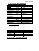
SCA818S Backplane User’s Guide B. Rear Connectors and LED Indicators B-1 Rear Connector/LED Indicator Locations Rear View SCA1 D12 D5 SCA#0 SCA4 SCA#1 D13 D6 SCA2 SCA#2 (*See below for rear connector/LED descriptions.) B-2 Connector/LED Indicator Descriptions B-2.1 Backplane Rear Connectors Rear Connector Specification SCA1 (Rear) SCA4 (Rear) SCA2 (Rear) SCSI HDD#0 (SCA#0) SCSI HDD#1 (SCA#1) SCSI HDD#2 (SCA#2) B-2.