742S 742i SC742 CHASSIS USER'S GUIDE 1.
SC742 Chassis User’s Guide The information in this User’s Guide has been carefully reviewed and is believed to be accurate. The vendor assumes no responsibility for any inaccuracies that may be contained in this document, makes no commitment to update or to keep current the information in this manual, or to notify any person or organization of the updates. Please Note: For the most up-to-date version of this manual, please see our web site at www.supermicro.com.
Chapter 1: Safety Information and Technical Specifications Table of Contents Chapter I: Safety Information and Technical Specifications .......... 1-4 1-1. Safety Information ............................................................................. 1-4 1-2. Technical Specifications .................................................................. 1-6 A. 742 SATA Back Panel ................................................................. 1-6 B. SCA742-E2 SCSI Dual Channel Back Panel (w/GEM318) .....
SC742 Chassis User’s Guide Chapter 1-Safety Information and Technical Specifications 1-1 Safety Information ! Electric Static Discharge (ESD) can damage electronic components. To prevent damage to your system board, it is important to handle it very carefully. The following measures are generally sufficient to protect your equipment from ESD.\ Static-Sensitive Devices • Use a grounded wrist strap designed to prevent static discharge.
Chapter 1: Safety Information and Technical Specifications STOP To avoid personal injury and property damage, please carefully follow all the safety steps listed below: Before accessing the chassis: 1. Turn off all peripheral devices connected to the SC742. 2. Press the power button to power off the system. 3. Unplug all power cords from the system or the wall outlets. 4. Disconnect all the cables and label the cables for easy identification. 5.
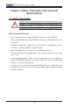
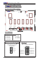
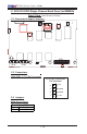
SC742 Chassis User’s Guide 1-2 Technical Specifications A. 742 SATA Back Panel A-1 Connector/Jumper Locations 199.70MM 742 SATA 1 1 D3 JP18 JP25 135.
Chapter 1: Safety Information and Technical Specifications A-3 Jumpers JP18: Buzzer Reset Buzzer Reset (JP18) Open Disabled Closed Enabled (*Default) JP25: Overheat LED Overheat Temperature (JP25) Pins Definition Open 450 C 1-2 500 C 2-3 550 C A-4 Connector/LED Indicator Locations (Rear Side) Activity LED Indicators LED# D12 D13 D14 D15 D18 D21 D22 Drive# SATA#0: Active SATA#1: Active SATA#2: Active SATA#3: Active SATA#4: Active SATA#5: Active SATA#6: Active 1-7 D22 SATA6 D21 SATA5 D18 Rear View (
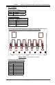
SC742 Chassis User’s Guide B. SCA 74-E2 SCSI Dual Channel Back Panel (W/GEM318) Front View (*Not Drawn to Scale) JP15 B-2 Connectors JP10/JP15: 4-Pin PWR Connectors 4-Pin PWR Connectors Pin Definitions B-3 Jumpers 4 +5V 3 Ground 2 Ground 1 +12V JP18: Buzzer Reset Buzzer Reset (JP18) Open Disabled Closed Enabled (*Default) SCSI Channel A Jumpers SCSI Channel B Jumpers Channel A Jumpers Jumpers Definition JP14 Ch.A Delay Start JP22 Ch.
Chapter 1: Safety Information and Technical Specifications B-4 Connector/LED Indicator Locations (Rear) Rear View (*Not drawn to scale) SCSI Drive Fail LED Indicators Drive Fail LED Indicators LED# D5 D6 D16 D17 D22 D23 D25 Drive ID# Channel A-ID#0 Channel A-ID#1 Channel A-ID#2 Channel B-ID#0 Channel B-ID#1 Channel B-ID#2 Channel B-ID#3 SCA# SCA 1: Fail SCA 2: Fail SCA 3: Fail SCA 4: Fail SCA 5: Fail SCA 6: Fail SCA 7: Fail SCSI Drive Activity LED Indicators Drive Activity LED Indicators LED# D12 D13
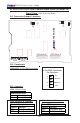
SC742 Chassis User’s Guide C.
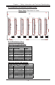
Chapter 1: Safety Information and Technical Specifications C-4 Connector/LED Indicator Locations (Rear) Rear View (*Not drawn to scale) SCSI Drive Fail LED Indicators Drive Fail LED Indicators Drive ID# ID#0 ID#1 ID#2 ID#3 ID#4 ID#5 ID#6 SCA# SCA 1: Fail SCA 2: Fail SCA 3: Fail SCA 4: Fail SCA 5: Fail SCA 6: Fail SCA 7: Fail SCSI Drive Activity LED Indicators Drive Activity LED Indicators LED# D12 D13 D14 D15 D20 D21 D22 Drive ID# ID#0 ID#1 ID#2 ID#3 ID#4 ID#5 ID#6 SCA# SCA 1: Active SCA 2: Active S
SC742 Chassis User’s Guide D SCSI (Super) GEM Driver Installation (*for the Windows OS) (*Note: This driver is not necessary for other Operating Systems. If you have two SCA backplanes, you will need to install the driver twice.) The driver is located on the Super Micro motherboard driver CD or is available for download from our FTP site: ftp://ftp.supermicro.com/driver/ Qlogic/ Follow the procedure below to install this driver to your system.
Chapter 1: Safety Information and Technical Specifications Notes 1-13
Chapter 2 Installation Instructions The special design of the SC742 chassis allows it to either be used as a tower or as a rackmount system. There are several versions of the chassis, which differ primarily in the power supply and IDE/SCSI configuration. Please refer to the following instructions when working on the SC742. I. Removing the Chassis Side Cover: You will need to remove the chassis side cover to: A. Remove or install drives into any of the 5 ¼” drive bays. B. Replace chassis fans. C.
A. Removing/Installing Drives into the 5 ¼” Drive Bays: Procedure: 1. With the side chassis cover removed, you have access to the 5 ¼” drive bays. 2. Remove the screws to the bay you wish to install or remove a component from. The chassis comes with dummy modules in all the bays to maintain proper airflow – these should remain in the chassis until you add a component. Note that the top two bays are combined into a single module.
B. Removing/Installing Chassis Fans into the 5 ¼” Drive Bays: Procedure: 1. To remove the hot-swap chassis fans, grasp the fan handle while squeezing the locking tab. Pull the fan unit up and out of the chassis. Reverse this procedure to install a fan (replace with the exact same type of fan). 2. If installing an extended ATX motherboard, you may need to remove the fan mounting bracket the fans are attached to for better access. To do so, first remove both fans by following step one.
II. Removing the Front Chassis Cover: You do not need to remove the front bezel to access the drives: Procedure 1. Push on the three tabs on the inside left side lip of the front chassis cover. Push the same side of the cover out about ½ inch. Push on the open side of the cover to remove it from the chassis (do not try to swing or pull it straight out after opening the left side). 2 1 Front Cover Push the tabs toward the lip and (1) push that side of the cover out from the chassis.
III. Removing the Top Chassis Cover and Chassis Feet to Install as Rackmount: You will need to remove the top chassis cover to add rack rails to the chassis: Note: Rail assemblies are optional. P/N: CSE-PT26B (black) and CSE-PT26. Procedure 1. Push the release tab in the center of the cover lip while pushing the cover toward the rear of the chassis at the same time. After the cover stops, lift it off. 2. Each chassis foot has a single screw.