SUPER ® The SC513 -L420 Series & the SC513-L260 Series SC513 CHASSIS USER'S GUIDE 1.
SC513 Chassis User’s Guide The information in this User’s Guide has been carefully reviewed and is believed to be accurate. The vendor assumes no responsibility for any inaccuracies that may be contained in this document, makes no commitment to update or to keep current the information in this manual, or to notify any person or organization of the updates. Please Note: For the most up-to-date version of this manual, please see our web site at www.supermicro.com.
Chapter 1: Safety Information and Technical Specifications Table of Contents Chapter I: Safety Information and Technical Specifications .......... 1-4 1-1. Electrical Safety Guidelines ............................................................. 1-4 1-2. General Safety Guidelines ............................................................... 1-5 1-3. ESD Safety Guidelines ....................................................................... 1-6 1-4. Operation Safety Guidelines .........................
SC513 Chassis User’s Guide Chapter 1-Safety Information and Technical Specifications 1-1 Electrical Safety Guidelines ! Warning: To avoid electrical shock, cords as follows: check the power Checking the Power Cords !Use the exact type of power cords as required. !Be sure to use the power cord(s) that came with safety certifications. !The power cord(s) must be compliant with the AC voltage requirements in your region.
Chapter 1: Safety Information and Technical Specifications Use rubber mats specifically designed as electrical insulators when working with computer systems. The power supply or power cord must include a grounding plug and must be plugged into grounded outlets. Motherboard Battery: CAUTION -Make sure not to install the onboard battery upside down to avoid possible explosion. Make sure that the positive side should be facing up on the motherboard.
SC513 Chassis User’s Guide 1-3 ESD Safety Guidelines ! Electric Static Discharge (ESD) can damage electronic components. To prevent damage to your system board, it is important to handle it very carefully. The following measures are generally sufficient to protect your equipment from ESD. Use a grounded wrist strap designed to prevent static discharge. Keep all components and printed circuit boards (PCBs) in their antistatic bags until ready for use.
Chapter 1: Safety Information and Technical Specifications STOP To avoid personal injury and property damage, please carefully follow all the safety steps listed below: Before accessing the chassis: 1. Turn off all peripheral devices connected to the SC513. 2. Press the power button to power off the system. 3. Unplug all power cords from the system or the wall outlets. 4. Disconnect all the cables and label the cables for easy identification. 5.
SC513 Chassis User’s Guide Before installing the chassis into a rack: 1. Make sure that the rack is securely anchored onto a unmovable surface or structure before installing the chassis into the rack. 2. Unplug the power cord(s) of the rack before installing the chassis into the rack. 3. Make sure that the system is adequately supported. Make sure that all the components are securely fastened to the chassis toprevent components falling off from the chassis. 4.
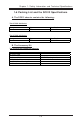
Chapter 1: Safety Information and Technical Specifications 1-6 Packing List and the SC513 Specifications A. The SC513 chassis contains the following: The SC513L-260 Series: Component Blower Qty 1 Part Number FAN-0059 Qty 3 Part Number FAN-0078 The SC513L-420 Series: Component Fan B.
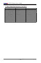
SC513 Chassis User’s Guide C. Power Supply Specifications of the SC513 Power supply spec Mfr. Model# Mfr. Part# Rated AC input voltage Rated input frequency Rated input current Rated output power Maximum rated BTU Nominal DC output +3.
Chapter 2: Chassis Description and Installation Instructions Chapter 2: Chassis Description and Installation Instructions 2-1 Chassis Description A. Contents of the Accessory Kit: The following items are included in the Accessory Kit: M/B A A. Pan head w/ lock 6-32 x 4.5 mm [0.177] DRIVE D E D. Pan head 6-32 x 5 mm [0.197] (*For 3.5" HDD) E. Round head M3 x 5 mm [0.197] (*For 2.5" HDD) RAIL (*Not included in the shipment) H G I G. Round head M4 x 4 mm [0.157] H. Flat head M5 x 12 mm [0.472] I.
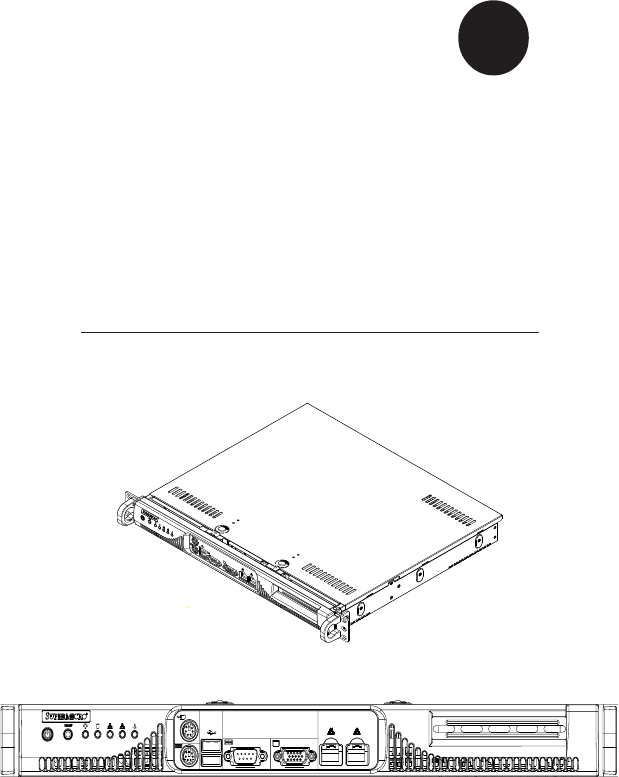
SC513 Chassis User’s Guide C. Chassis Front View and the Front Control Panel Chassis Front View 1 2 1. Front Panel and I/O Device Definitions 1. Front Panel LED Indicators 2. I/O Devices 3A. Two 2.5" Drives (*SC513L-420) 3B. One 3.5" Drive (*SC513L-260) Front Panel LED Indicators 1 1A 1B 1C 1D 1E 1F 1G LED Button Definitions 1A. Power Button 1B. Reset Button 1E. LAN1 1F. LAN2 1C. Power Indicator 1G. Overheat 1D.
Chapter 2: Chassis Description and Installation Instructions Front Control Panel LED Button Descriptions /(' %XWWRQ 3RZHU &RORU *UHHQ +'' $PEHU /$1 /$1 *UHHQ 2YHUKHDW 5HG &RQGLWLRQ 2Q 2II %OLQN 2II 2Q %OLQN 2II 2Q 2II 'HVFULSWLRQ 6\VWHP 2Q 6\VWHP 2II +'' $FWLYLW\ 1R $FWLYLW\ /LQNHG /$1 $FWLYLW\ 'LVFRQQHFWHG 6\VWHP 2YHUKHDW 6\VWHP 1RUPDO 2. I/O Devices/Components 2 2A 2B 2H 2C 2D 2E 2F 2G 2A. Mouse (Green) 2B. Keyboard (Purple) 2C. USB 0/1 2D.
SC513 Chassis User’s Guide D.
Chapter 2: Chassis Description and Installation Instructions 2-2 Chassis Installation A. Important Safety Guidelines STOP This product shall only be accessed, assembled and serviced by technically qualified personnel or technicians. To avoid personal injury and property damage, please read all the information provided in Chapter 1, and carefully follow all the Safety Guidelines listed before accessing or servicing the SC513 or its components.
SC513 Chassis User’s Guide C. Removing the Top Chassis Cover and the HDD Tray Bracket from the chassis Before installing a hard drive into the chassis, you need to remove the top cover and the HDD tray bracket from the chassis. (*Note: Removing the top cover when the system is running will degrade thermal performance.) Procedures 1. Remove the screw from the back panel of the chassis as shown in the picture. 2. Press the two tabs on the top cover to release the cover from the locking position. 3.
Chapter 2: Chassis Description and Installation Instructions D. Removing the HDD Drive Tray Housing and Installing Hard Disks After the HDD Drive Tray Bracket is removed from the chassis, you can install HDDs into the HDD Drive Housing. Procedures 1. Remove the four screws on each side of HDD Tray Bracket as shown in the picture. 2. Once the eight screws are removed, you can remove the cover from the HDD 1 tray. 2 3 1 3.
SC513 Chassis User’s Guide E. Installing the Motherboard Be sure to disconnect the power supply before accessing or installing the motherboard into the chassis. (Refer to Chapter 1 for Safety Guidelines.) Procedures 1. Lay the chassis on a flat surface. 2. Locate the CPU location(s). If you have a UP system, be sure to install heatsink brackets on the reverse side of the CPU. (If you have a DP system, please ignore this step because the heatsink brackets are pre-installed by the manufacturer.) 3.
Chapter 2: Chassis Description and Installation Instructions F. Installing and Un-installing the Heatsink Mechanism Heatsinks are heavy. Please handle with care!! ! *Note: Be sure to use Heatsink (# SNK-P0011) for a UP system, and use Heatsink (#SNK-P0007) for a DP System. Procedures: Heatsink Installation 1. Do not apply any thermal grease to the heatsink or the CPU die; the required amount of thermal grease has already been applied. 2.
SC513 Chassis User’s Guide G. Removing and Installing the Front Bezel To access the front panel, you will need to remove the front bezel from the chassis. Be sure to install the front bezel before operating the system. Procedures (-Removing the front bezel) 1. Locate the four release tabs in the chassis as shown in the picture. 2. Gently press the release tabs to loosen the front bezel. 3. Once the front bezel is loosened, remove it from the chassis.
Chapter 2: Chassis Description and Installation Instructions H-1. Installing the Cooling Fan Module and the Air Shroud for a DP System After the motherboard and the heatsink(s) have been installed in the chassis, you need to install cooling fans and an air shroud for proper system cooling. Procedures (*Installing the Cooling Fan Module for a DP System) 1. Locate three mounting tabs on the cooling fan module and their corresponding module mounting holes on the chassis as shown in the picture below. 2.
SC513 Chassis User’s Guide H-2. Installing the Blower and the Air Shroud for a UP System After the motherboard and the heatsink(s) have been installed in the chassis, you need to install cooling fans and an air shroud for proper system cooling. Procedures (*Installing the Blower for a UP System) 1. Locate two mounting holes on the rubber pad and their corresponding tabs on the chassis as shown in the picture below. 2.
Chapter 2: Chassis Description and Installation Instructions I. Installing the Chassis Inner Rails (*Optional for the SC513) (*Note: if your chassis does not come with chassis rails, please follow the procedure listed on the last page to install the SC513 directly into the rack.) Please make sure that the chassis covers and chassis rails are installed on the chassis before you install the chassis into the rack.
SC513 Chassis User’s Guide 3. Locate the three holes on each side of the chassis and locate the three corresponding holes on each of the inner rail. 3 G 4. Attach an inner rail to each side of the chassis and secure the inner rail to the chassis by inserting three Type G screws through the holes on each side of the chassis and the inner rail. (Refer to Page 2-1 for the Type G screw.) 5. Repeat the above steps to install the other rail on the chassis.
Chapter 2: Chassis Description and Installation Instructions J-1 Rack Installation for the Traditional UP Design (*Optional for the SC513) After you have installed the inner rails on the chassis, you are ready to install the outer rails of rail assemblies to the rack. (* The rails are designed to fit in the racks with the depth of 28" to 33".) Procedures 1. In the package, locate a pair of front (-short) and rear (-long) brackets.
SC513 Chassis User’s Guide 7. Slide the SC513 chassis into the rack as shown below: (The SC513 may not slide into the rack smoothly or easily when installed the first time. However, some adjustment to the slide assemblies might be needed for easy installation.) 8. You will need to release the safety taps on both sides of the chassis in order to completely remove the chassis out of the rack.
Chapter 2: Chassis Description and Installation Instructions J-2 Rack Installation for the Open-Rack Design (*Optional for the SC513) After you have installed the inner rails on the chassis, you are ready to install the outer rails of rail assemblies to the rack. (* The rails are designed to fit in the racks with the depth of 28" to 33".) Procedures 1. In the package, locate a pair of front (-short) and rear (-long) brackets.
SC513 Chassis User’s Guide 3. Attach the front (-short) bracket to the front end of the rack, and secure it to the rack with two Type H screws and Type I washers as shown below. 4. Attach the rear (-long) bracket to the rear end of the rack, and secure it to the rack with two Type H screws and Type I washers as shown below. Repeat the same steps to install the other outer rail to the other side of rack.
Chapter 2: Chassis Description and Installation Instructions 5. Measure the depth of your rack and adjust the length of the rails accordingly. Then, secure the rails to the chassis with Type G screws. 6. Slide the inner rails which are attached to the chassis into the outer rails on the rack.
SC513 Chassis User’s Guide K. Installing the SC513 into the Racks STOP (*Note: Please make sure that all components and all chassis covers are properly installed in the chassis before you install the SC513 into the racks; otherwise, out-of warranty damage may occur.) Procedures 1. Slide the SC513 into the racks and secure it with two screws on each side of the rack as shown in the picture.