SUPER ® SC113 Chassis Series SC113TQ-700UB SC113TQ-R650UB SC113TQ-700CB SC113TQ-R650CB SC113TQ-563CB SC113TQ-563UB SC113TQ-560UB USER’S MANUAL 1.
SC113 Chassis Manual The information in this User’s Manual has been carefully reviewed and is believed to be accurate. The vendor assumes no responsibility for any inaccuracies that may be contained in this document, makes no commitment to update or to keep current the information in this manual, or to notify any person or organization of the updates. Please Note: For the most up-to-date version of this manual, please see our web site at www.supermicro.com. Super Micro Computer, Inc.
Preface Preface About This Manual This manual is written for professional system integrators and PC technicians. It provides information for the installation and use of the SC113 1U chassis. Installation and maintenance should be performed by experienced technicians only. Supermicro's SC113 1U chassis is optimized for high-end, high-performance applications. It is an efficient 1U rackmount design optimized for best price/performance. It includes eight hot-swappable 2.
SC113 Chassis Manual Manual Organization Chapter 1 Introduction The first chapter provides a checklist of the main components included with this chassis and describes the main features of the SC113 chassis. This chapter also includes contact information. Chapter 2 System Safety This chapter lists warnings, precautions and system safety. Thoroughly familiarize yourself with this chapter for a general overview of the safety precautions that should be followed before installing and servicing this chassis.
Preface Table of Contents Preface About This Manual......................................................................................................... iii Chapter 1 Introduction 1-1 Overview.......................................................................................................... 1-1 1-2 Shipping List..................................................................................................... 1-1 1-3 Chassis Features.......................................................
SC113 Chassis Manual 4-5 Power Supply LEDs......................................................................................... 4-5 Chapter 5 Chassis Setup and Maintenance 5-1 Overview.......................................................................................................... 5-1 5-2 Installation and Maintenance Procedures........................................................ 5-1 Installation...........................................................................................
Preface Inner Rail Extension......................................................................................... 6-5 Outer Rails....................................................................................................... 6-6 Installing the Chassis into a Telco rack...........................................................
SC113 Chassis Manual Notes viii
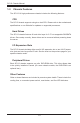
Chapter 1 Introduction Chapter 1 Introduction 1-1 Overview Supermicro’s SC113 1U chassis features a unique and highly-optimized design. The chassis is equipped with high efficiency power supply. High-performance fans provide ample optimized cooling for the dual processor modules and eight hot-swappable drive bays offer maximum storage capacity in a 1U form factor. Only SAS or enterprise SATA HDDs are recommended for use in the SC113 chassis.
SC113 Chassis Manual 1-3 Chassis Features The SC113 1U high-performance chassis includes the following features: CPU The SC113 chassis supports a single or dual CPU. Please refer to the motherboard specifications on our Website for updates on supported processors. Hard Drives The SC113 chassis features 8 hard drive bays for 2.5" hot-swappable SAS/SATA drives. Once setup correctly, these drives can be removed without powering down the server.
Chapter 1 Introduction 1-4 Contacting Supermicro Headquarters Address: Super Micro Computer, Inc. 980 Rock Ave. San Jose, CA 95131 U.S.A. Tel: +1 (408) 503-8000 Fax: +1 (408) 503-8008 Email: marketing@supermicro.com (General Information) support@supermicro.com (Technical Support) Web Site: www.supermicro.com Europe Address: Super Micro Computer B.V. Het Sterrenbeeld 28, 5215 ML 's-Hertogenbosch, The Netherlands Tel: +31 (0) 73-6400390 Fax: +31 (0) 73-6416525 Email: sales@supermicro.
SC113 Chassis Manual 1-5 Returning Merchandise for Service A receipt or copy of your invoice marked with the date of purchase is required before any warranty service will be rendered. You can obtain service by calling your vendor for a Returned Merchandise Authorization (RMA) number. When returning to the manufacturer, the RMA number should be prominently displayed on the outside of the shipping carton, and mailed prepaid or hand-carried.
Chapter 2 System Safety Chapter 2 System Safety 2-1 Overview This chapter provides a quick setup checklist to get your chassis up and running. Following the steps in the order given should enable you to have your chassis set up and operational within a minimal amount of time. This quick setup assumes that you are an experienced technician, famailiar with common concepts and terminology.
SC113 Chassis Manual 2-4 Electrical Safety Precautions Basic electrical safety precautions should be followed to protect yourself from harm and the SC113 from damage: • • • • • • • • • Be aware of the locations of the power on/off switch on the chassis as well as the room’s emergency power-off switch, disconnection switch or electrical outlet. If an electrical accident occurs, you can then quickly remove power from the system. Do not work alone when working with high voltage components.
Chapter 2 System Safety radiation exposure, do not open the enclosure or use the unit in any unconventional way. 2-5 • • • • • 2-6 General Safety Precautions Keep the area around the chassis clean and free of clutter. Place the chassis top cover and any system components that have been removed away from the system or on a table so that they won’t accidentally be stepped on.
SC113 Chassis Manual • • • • • Do not let components or PCBs come into contact with your clothing, which may retain a charge even if you are wearing a wrist strap. Handle a board by its edges only; do not touch its components, peripheral chips, memory modules or contacts. When handling chips or modules, avoid touching their pins. Put the serverboard and peripherals back into their antistatic bags when not in use.
Chapter 3 Chassis Components Chapter 3 Chassis Components 3-1 Overview This chapter describes the most common components included with your chassis. Some components listed may not be included or compatible with your particular chassis model. For more information, see the installation instructions detailed later in this manual. 3-2 Components Chassis The chassis includes eight 2.5" hard drive bays, and one slim DVD-ROM drive. (On some chassis models, the DVD-ROM is an optional item).
SC113 Chassis Manual Power Supply Each SC113 chassis model includes one or two high-efficiency power supplies rated at 560, 650 or 700 Watts. "R" models include a second redundant, hot-swappable power supply. In the unlikely event your power supply fails, replacement is simple and can be done without tools. Air Shroud Air shrouds are shields, usually plastic, that channel air directly to where it is needed. Always use the air shroud included with your chassis.
Chapter 4 System Interface Chapter 4 System Interface 4-1 Overview There are several LEDs on the control panel and on the drive carriers that provide system and component status. This chapter explains the meanings of all LED indicators and the appropriate responses that need to be taken.
SC113 Chassis Manual 4-2 Control Panel Buttons The SC113 chassis includes two or three push-buttons located on the front panel: A reset button, a power on/off button, and a UID button • • • Reset: The reset button is used to reboot the system. Power: The main power switch is used to apply or remove power from the power supply to the server system. Turning off system power with this button removes the main power but keeps standby power supplied to the system.
Chapter 4 System Interface 4-3 Control Panel LEDs The control panel located on the front of the SC113 chassis has up to five LEDs. These LEDs provide critical information related to different parts of the system. This section explains what each LED indicates when illuminated and any action that may be required. • Universal Information LED: The Universal Information LED is used to indicate a fan failure, power failure, overheat condition, or to identify the unit within a large rack installation.
SC113 Chassis Manual • NIC2: Indicates network activity on GLAN2 when flashing. • NIC1: Indicates network activity on GLAN1 when flashing. • • 4-4 HDD: Indicates IDE channel activity. SAS/SATA drive and/or DVD-ROM drive activity when flashing. Power: Indicates power is being supplied to the system's power supply units. This LED should normally be illuminated when the system is operating. Drive Carrier LEDs The SC113 chassis uses SAS/SATA drives.
Chapter 4 System Interface nection to the SATA backplane enables this LED to blink on and off when that particular drive is being accessed. • 4-5 Red: The red LED indicates a SAS/SATA drive failure. If one of the SAS/SATA drives fail, you should be notified by your system management software. Power Supply LEDs This chassis provides several options which may include hot-swappable, coldswappable, and redundant power supplies.
SC113 Chassis Manual Notes 4-6
Chapter 5 Chassis Setup and Maintenance Chapter 5 Chassis Setup and Maintenance 5-1 Overview This chapter covers the steps required to install components and perform maintenance on the chassis. The only tool you will need to install components and perform maintenance is a Phillips screwdriver. Print this page to use as a reference while setting up your chassis.
SC113 Chassis Manual 5-3 Removing the Chassis Cover 3 2 Figure 5-1: Removing the Chassis Cover Removing the Chassis Cover: 1. Remove the screws securing the top cover to the chssis. 2. Slide the cover toward the rear of the chassis. 3. Lift the cover up and off of the chassis. ! Warning: Except for short periods of time, do NOT operate the server without the cover in place. The chassis cover must be in place to allow proper airflow and prevent overheating.
Chapter 5 Chassis Setup and Maintenance 5-4 Installing and Removing Hard Drives 2 1 Figure 5-2: Removing Hard Drive The SC113 chassis excepts eight hot-swappable hard drives. Only SAS or enterprise SATA HDDs are recommended. Removing Hard Drive Carriers from the Chassis 1. Press the release button on the drive carrier. This extends the drive carrier handle. 2. Use the handle to pull the drive out of the chassis. Note that only enterprise level HDDs are recommended for use in the SC113 chassis.
SC113 Chassis Manual Figure 5-3: Removing the Dummy Drive from the Hard Drive Carrier Installing a Hard Drive into a Drive Carrier 1. Remove the dummy drive, which comes pre-installed in the drive carrier, by removing the screws securing the dummy drive to the carrier. Note that these screws cannot be reused on the actual 2.5" hard drive. 2. Insert a drive into the carrier with the PCB side facing down and the connector end toward the rear of the carrier. 3.
Chapter 5 Chassis Setup and Maintenance 5-5 DVD-ROM Drive Installation The SC113 chassis models include a DVD-ROM, which is usually pre-installed. Installing or Replacing a DVD-ROM Drive 1. Power down the system and if necessary, remove the server from the rack and pull the mini-bezel (grate) from the DVD-ROM drive bay. 2. Remove the chassis cover. 3. Unplug the drives power and data cables from the motherboard and/or backplane. 4.
SC113 Chassis Manual 8. Reconnect the data and power cables. 9. Replace the chassis cover (replace the server in the rack, if necessary) and power up the system. 5-6 Removing the Backplane The SC113 chassis backplane is located behind the hard drives and in front of the front system fans. In order to change the jumper settings on the backplane, it may be necessary to remove the backplane from the chassis. Removing the Backplane from the Chassis 1. Power down and unplug the system from any power source.
Chapter 5 Chassis Setup and Maintenance 5-7 Backplane Installation Installing the Backplane 1. Slide the backplane into the chassis as shown, inserting the lower edge of the backplane into the clips on the floor of the chassis. 2. Align the mounting holes in the backplane with the mounting holes in the chassis 3. Secure the backplane to the chassis using the five screws provided with the backplane. 4. Connect the wiring to the backplane.
SC113 Chassis Manual 5-8 Installing the Motherboard Optional Standoffs Figure 5-7: Chassis Standoffs Permanent and Optional Standoffs Standoffs prevent short circuits by creating space between the motherboard and the chassis surface. The SC113 chassis includes permanent standoffs in locations used by most motherboards. These standoffs accept the rounded Phillips head screws included in the SC113 accessories packaging.
Chapter 5 Chassis Setup and Maintenance Motherboard Installation Installing the Motherboard 1. Review the documentation that came with your motherboard. Become familiar with component placement, requirements, and precautions. 2. Disconnect the power supply and lay the chassis on a flat surface. 3. Open the chassis cover. 4. If necessary, remove the riser card. To do this, remove the two screws holding the card in place and lift the card from the chassis. 5.
SC113 Chassis Manual Expansion Card Setup SC113 chassis includes I/O slots for add-on cards and expansion cards. "C" models (like SC113TQ-700CB) include one full height slot. "U" model chassis include two full-height expansion slots and one low-profile expansion slot. Note: You must use a riser card to install expansion cards into any SC113 chassis. Riser cards are sold separately. For the latest compatibility and performance information, visit our website at: http://www.supermicro.com.
Chapter 5 Chassis Setup and Maintenance Riser Card Riser Card Bracket Screws Figure 5-10: Chassis with a Riser Card Installing an Expansion Card 1. Confirm that you have the correct riser card for your chassis model and the add-on card includes a standard bracket. 2. Remove the chassis cover. 3. Install the riser card onto the bracket. Insert the card and bracket into the appropriate slot on the motherboard. Secure the riser bracket to the chassis using screws as illustrated. 4.
SC113 Chassis Manual 5-9 Installing the Air Shroud Air shrouds concentrate airflow to maximize fan efficiency. The SC113 chassis air shroud does not require screws for installation. Figure 5-11: Air Shroud Installation Air Shroud Installation 1. Align the air shroud with the CPU, memory card and fan locations. 2. Check the air shroud and serverboard components, removing the break-away piece from the side of the air shroud if required. 3. Place the air shroud into the chassis.
Chapter 5 Chassis Setup and Maintenance Checking the Airflow Check the Airflow 1. Make sure there are no objects to obstruct airflow in and out of the server. In addition, if you are using a front bezel, make sure the bezel's filter is replaced periodically. 2. Do not operate the server without drives or drive trays in the drive bays. Use only recommended server parts. 3. Make sure no wires or foreign objects obstruct the airflow through the chassis.
SC113 Chassis Manual 5-10 System Fans Figure 5-12: System Fan Four heavy-duty fans provide cooling for the chassis. These fans circulate air through the chassis as a means of lowering the chassis' internal temperature. The SC113 chassis contains counter-rotating fans. Each fan unit is actually made up of two fans joined back-to-back, which rotate in opposite directions. This counter-rotating action generates exceptional airflow and works to dampen vibration levels.
Chapter 5 Chassis Setup and Maintenance 3 Figure 5-13: Chassis Fans The SC113 chassis includes four pre-installed fans. Two additional open slots are available so that up to two more fans may be added. Replacing a System Fan 1. If necessary, open the chassis while the power is running to determine which fan has failed. Never run the server for an extended period of time with the chassis open. 2. Turn off the power to the system and unplug the system from the outlet. 3.
SC113 Chassis Manual 5-11 Power Supply Depending on your chassis model, the SC113 chassis has a 560W, 650W or 700W power supply. This power supply is auto-switching capable. They automatically sense and operate at a 100v to 240v input voltage. An amber light will be illuminated on the power supply when the power is off. An illuminated green light indicates that the power supply is operating.
Chapter 5 Chassis Setup and Maintenance Release Tab Figure 5-14: Removing the Power Supply Replacing the Power Supply 1. Power down the server and unplug the power cord. If your chassis includes a redundant power supply (at least two power modules), you can leave the server running and remove only one power supply. 2. Push the release tab (on the back of the power supply) as illustrated. 3. Pull the power supply out using the handle provided. 4. Replace the failed power module with the same model. 5.
SC113 Chassis Manual Notes 5-18
Chapter 6 Rack Installation Chapter 6 Rack Installation 6-1 Overview This chapter provides a quick setup checklist to get your chassis up and running. Following these steps in the order given should enable you to have the system operational within a minimum amount of time. 6-2 Unpacking the System You should inspect the box the chassis was shipped in and note if it was damaged in any way. If the chassis itself shows damage you should file a damage claim with the carrier who delivered it.
SC113 Chassis Manual ! • Warnings and Precautions! ! Rack Precautions Ensure that the leveling jacks on the bottom of the rack are fully extended to the floor with the full weight of the rack resting on them. • In single rack installation, stabilizers should be attached to the rack. • In multiple rack installations, the racks should be coupled together. • • • • • • • • Always make sure the rack is stable before extending a component from the rack.
Chapter 6 Rack Installation Rack Mounting Considerations Ambient Operating Temperature If installed in a closed or multi-unit rack assembly, the ambient operating temperature of the rack environment may be greater than the ambient temperature of the room. Therefore, consideration should be given to installing the equipment in an environment compatible with the manufacturer’s maximum rated ambient temperature (Tmra).
SC113 Chassis Manual 6-4 Rack Mounting Instructions This section provides information on installing the SC113 chassis into a rack unit with the rails provided. There are a variety of rack units on the market, which may mean the assembly procedure will differ slightly. You should also refer to the installation instructions that came with the rack unit you are using. NOTE: This rail will fit a rack between 26" and 33.5" deep.
Chapter 6 Rack Installation 1 2 3 Figure 6-2: Identifying the Sections of the Rack Rails (right side rail shown) Inner Rail Extension The SC113 chassis includes a set of inner rails in two sections: inner rails and inner rail extensions. The inner rails are pre-attached and do not interfere with normal use of the chassis if you decide not to use a server rack. Attach the inner rail extension to stabilize the chassis within the rack. Installing the Inner Rails 1.
SC113 Chassis Manual Secure to the Front of the Rack Attach Outer Racks together Secure to the Rear of the Rack Figure 6-3: Assembling the Outer Rails Outer Rails Installing the Outer Rails to the Rack 1. Attach the shorter outer rail to the outside of the longer outer rail. You must align the pins with the slides. Also, both bracket ends must face the same direction. 2. Adjust both the shorter and longer brackets to the proper distance so that the rail fits snugly into the rack. 3.
Chapter 6 Rack Installation 3 3 2 SCALE 0.
SC113 Chassis Manual Figure 6-5: Installing the Server into a Rack Installing the Chassis into a Rack 1. Confirm that chassis includes the inner rails and inner rail extensions. Alsoconfirm that the outer rails are installed on the rack. 2. Align the chassis inner rails with the front of the out rails on the rack. 3. Slide the chassis rails into the rack rails, keeping the pressure even on both sides (you may have to depress the locking tabs when inserting).
Chapter 6 Rack Installation Installing the Chassis into a Telco rack To install the chassis into a Telco type rack, use two L-shaped brackets on either side of the chassis (four total). First, determine how far follow the server will extend out the front of the rack. Larger chassis should be positioned to balance the weight between front and back. If a bezel is included on your server, remove it.
SC113 Chassis Manual Notes 6-10
Appendix A Chassis Cables Appendix A SC113 Chassis Cables A-1 Overview This appendix lists supported cables for your system. It only includes the most commonly used components and configurations. For more compatible cables, refer to the manufacturer of the motherboard you are using and our Web site at: www. supermicro.com.
SC113 Chassis Manual A-3 Compatible Cables These cables are compatible with the SC113 chassis. This section lists cables included with the SC113 chassis packages. Alternate SAS/SATA Cables Some compatible motherboards have different connectors. If your motherboard has only one SAS connector that the SAS/SATA cables must share, use one of the following cables. These cables must be purchased separately. Cable Name: SAS Cable Quantity: 1 Part #: CBL-0175L Alt.
Appendix A Chassis Cables Extending Power Cables Although Supermicro chassis are designed with to be efficient and cost-effective, some compatible motherboards have power connectors located in different areas. To use these motherboards you may have to extend the power cables to the motherboards. To do this, use the following chart as a guide. Power Cable Extenders Number of Pins Cable Part # Length 24-pin CBL-0042 7.9” (20 CM) 20-pin CBL-0059 7.9” (20 CM) 8-pin CBL-0062 7.
SC113 Chassis Manual Notes A-4
Appendix B Power Supply Specifications Appendix B SC113 Power Supply Specifications This appendix lists power supply specifications for your chassis system. SC113TQ-R700UB 700W/750W (80 PLUS Gold Certified) MFR Part # PWS-704P-1R AC Voltage 700W: 100 - 140 V, 50-60 Hz, 8.5 - 6 Amp 750W: 180 - 240 V, 60-50 Hz, 5 - 3.8 Amp DC Output 3 Amp +5V standby DC Output 700W: 58 Amp at 100-140V +12V 750W: 62 Amp at 180-240Vp +5V: 25 Amp With Power +3.3V: 25 Amp Distributor -12V: 0.
SC113 Chassis Manual Notes B-2
Appendix C SAS-113TQ Backplane Specifications Appendix C SAS-113TQ Backplane Specifications To avoid personal injury and property damage, carefully follow all the safety steps listed below when accessing your system or handling the components. C-1 ESD Safety Guidelines Electrostatic Discharge (ESD) can damage electronic components. To prevent damage to your system, it is important to handle it very carefully. The following measures are generally sufficient to protect your equipment from ESD.
SC113 Chassis Manual C-3 An Important Note to Users All images and layouts shown in this user's guide are based upon the latest backplane revision available at the time of publishing. The card you have received may or may not look exactly the same as the graphics shown in this manual. C-4 Introduction to the SAS-113TQ Backplane The SAS-113TQ backplane has been designed to utilize the most up-to-date technology available, providing your system with reliable, high-quality performance.
Appendix C SAS-113TQ Backplane Specifications Connectors, Jumpers and LEDs C-5 Front Connectors 1 1 GND 4 +5V SB#1 48 JP46 2 14 2 JP29 5 6 J6 JP33:M ODE SEL 1-2:SGPIO 2-3:I2C UPGRADE 1 C285 33 #1 12 #3 JP45 J8 I2C#2 9072 RST M H2 + GND JP51 SB#2 +12V M H4 JP52 C5 10 #5 49 JP33 M H1 R259 J10 J14 BUZZER RST 5 7 +5V + GND JP10 GND C6 JP13 1 + C4 J16 C98 + C137 M H3 J12 + 19 M H5 +12V + 8 J5 J7 JP44 1 M H6 64 11 Figure C-1: Front Connectors
SC113 Chassis Manual C-6 Front Connector and Pin Definitions #1. Backplane Main Power Connectors Backplane Main Power 4-Pin Connector The 4-pin connectors designated JP10, provide power to the backplane. See the table on the right for pin definitions. Pin# 1 2 and 3 4 Definition +12V Ground +5V #2 Upgrade Connector The upgrade connector, designated JP46 is for diagnostic purposes only. This connector should only be used by a certified and experienced technician. #3.
Appendix C SAS-113TQ Backplane Specifications #6 and #7. I2C Connectors The I C connectors, designated JP44 and JP45, are used to monitor HDD activity and status. See the table on the right for pin definitions. I2C Connector Pin Definitions 2 #8 - #15. SAS/SATA Connectors The SAS/SATA connectors are numbered 0 through 7. Each may be connected to the system with a SAS or SATA cable.
SC113 Chassis Manual C-7 Front Jumper Locations and Settings +5V +12V GND GND +5V UPGRADE 1 JP46 2 5 6 J6 JP51 JP29 33 #1 M H1 R259 J10 J14 BUZZER RST 49 JP33 + J16 C98 + C4 9072 RST 48 #3 #5 JP45 SB#1 J8 C5 C6 I2C#2 M H2 JP33:M ODE SEL 1-2:SGPIO 2-3:I2C M H5 C137 JP29 JP33 M H4 JP52 C285 J12 SB#2 JP13 1 + GND M H3 + GND JP10 +12V + + JP18 J5 J7 JP44 1 M H6 64 #0 #2 #4 #6 #7 REV 1.
Appendix C SAS-113TQ Backplane Specifications I2C and SGPIO Modes and Jumper Settings This backplane can utilize I2C or SGPIO. SGPIO is the default mode and can be used without making changes to your jumpers. The following information details which jumpers must be configured to use I2C mode or restore your backplane to SGPIO mode.
SC113 Chassis Manual 2-4 Rear Connectors and LED Indicators SAS #1 SAS #5 SAS #3 ACT#3 C CA C A A C C ACT#6 CA CA C CA J13 7 A A A CA C 22 SAS #4 SAS #2 SAS #0 8 A CA C CA A C CA A C106 7 SAS#7 FAIL#2 22 D23 8 7 SAS#6 D7 D5 FAIL#0 22 SAS#4 21 7 ACT#2 D14 9 8 SAS#2 33 D22 7 J4 ACT#0 D12 SAS#0 27 7 R149 8 7 J1 D20 D8 D6 FAIL#1 J2 R150 D15 SAS#5 21 SAS#3 33 9 D13 SAS#1 27 FAIL#6 8 22 J15 SAS #6 8 7 22 SAS #7 Figure C-4: Rear Co
Appendix C SAS-113TQ Backplane Specifications Notes C-9
SC113 Chassis Manual Disclaimer (cont.) The products sold by Supermicro are not intended for and will not be used in life support systems, medical equipment, nuclear facilities or systems, aircraft, aircraft devices, aircraft/emergency communication devices or other critical systems whose failure to perform be reasonably expected to result in significant injury or loss of life or catastrophic property damage.