
User`s manual


2-18
C2SBC-Q User's Manual
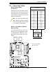
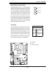
FAN1
JI2C2
JWOR
JPL1
JF1
JWD
JLED
Battery
DIMM1A
DIMM2A
DIMM1B
DIMM2B
I-SATA2
I-SATA3
SPEAKER
COM1
KB/MOUSE
CPU Fan
VGA
USB
2/3/4/5
Audio
J41
LGA 775 CPU
Slot7 PCI-E x16
Slot6 PCI-33MHz
JPL2
Slot3 PCI-33MHz
Slot2 PCI-33MHz
JP2
Buzzer
Slot1 PCI-33MHz
JPUSB2
IDE
FP USB 8/9
FP USB 6/7
I-SATA4
I-SATA5
JL1
LE1
Intel Q35
Intel ICH9
Audio CTRL
CD-IN
COM4
Front Audio
W83627DHG
Printer
S I/O 1
IDE CTRL
ITE 8213
COM3
COM2
USB 10
USB 11
JWOL
I-SATA0
I-SATA1
FAN2
W83627DHG
S I/O 2
Fan3
JPUSB1
LAN 1
Slot5 PCI-E x4
Slot4 PCI-33MHz
JP5
JI2C1
JSMB
LAN 2 CTRL
LAN 1 CTRL
JBT1
USB
0/1
LAN 2
ATX Power
C2SBC-Q
PWR SMB
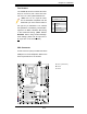
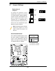
Pin Defi nitions
Pin# Defi nition
1 Data
2 Ground
3 Clock
4 No connection
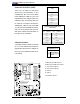
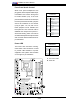
A. Speaker/Buzzer
B. SM Bus Header
Speaker
A Speaker/Buzzer header is located
on the motherboard. See the table on
the right for speaker pin defi nitions.
Note: The speaker connector pins
are for use with an external speaker.
If you wish to use the onboard
speaker, you should close pins 3-4
with a jumper.
Speaker Connector
Pin Defi nitions
Pin Setting Defi nition
Pins 3-4 Internal Speaker
Pins 1-4 External Speaker
SMB
The System Management Bus Header
(For the PCI bus) is located at JSMB
near the CPU fan. Connect the ap-
propriate cable here to utilize SMB on
your system. See the table on the right
for pin defi nitions.
A
B