
User's and BIOS Manual (1.0b)

Chapter 5: Advanced Motherboard Setup
5-15
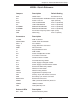
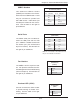
Fan Headers
The H8SSL-i has fi ve 3-pin fan head-
ers. Fan speed is controlled via Ther-
mal Management with a BIOS setting
(refer to Chapter 4). See the table on
the right for pin defi nitions.
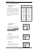
Serial Ports
The COM1 serial port is located be-
tween the USB ports and the VGA
port. COM2 is a header located near
the SATA0 port (see motherboard
layout for location). See the table on
the right for pin defi nitions.
Fan Header
Pin Defi nitions
(FAN1-5)
Pin# Defi nition
1 Ground
2 +12V
3 Tachometer
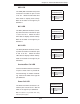
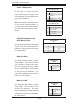
USB2/3 Headers
Two additional USB2.0 headers
(USB2/3) are included on the mother-
board near the COM2 header. These
may be connected to provide front
side USB access. USB cables (not
included) are needed for the connec-
tions. See the table on the right for
pin defi nitions.
Extra Universal Serial Bus Headers
Pin Defi nitions (USB2/3)
USB2
Pin # Defi nition
USB3/4
Pin # Defi nition
1 +5V 1 +5V
2 PO- 2 PO-
3 PO+ 3 PO+
4 Ground 4 Ground
5 Key 5 No connection
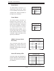
Overheat LED (JOH1)
Connect an LED to the JOH1 header
to provide warning of chassis over-
heating. See the table on the right
for pin defi nitions.
Overheat LED
Pin Defi nitions
(JOH1)
Pin# Defi nition
1 +5V
2 OH Active
Note: Pin 10 is included on the header but not on
the port. NC indicates no connection.
Serial Port Pin Defi nitions
(COM1/COM2)
Pin # Defi nition Pin # Defi nition
1 DCD 6 DSR
2 RXD 7 RTS
3TXD 8CTS
4 DTR 9 RI
5 Ground 10 NC