
User's and BIOS Manual (1.0b)

Chapter 5: Advanced Motherboard Setup
5-7
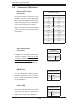
5-5 I/O Ports
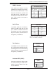
The I/O ports are color coded in conformance with the PC 99 specifi cation. See
Figure 5-3 below for the colors and locations of the various I/O ports.
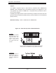
Figure 5-3. Rear Panel I/O Ports
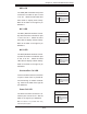
5-6 Installing Memory
CAUTION
Exercise extreme care when installing or removing memory modules
to prevent any possible damage.
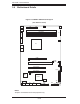
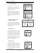
1. Insert each memory module vertically into its slot, beginning with CPU1 slot 1A,
then 2A, etc.. Pay attention to the notch along the bottom of the module to prevent
inserting the module incorrectly (see Figure 5-4). See support information below.
2. Gently press down on the memory module until it snaps into place.
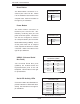
Note: each processor has its own built-in memory controller, so CPU2 DIMMs
cannot be addressed if only a single CPU is installed. 256 MB, 512 MB, and 1 GB
memory modules are supported.
Mouse (Green)
Keyboard
(Purple)
VGA Port (Blue) COM1 Port
(Turquoise)
JLAN1 / JLAN2
USB 0/1 Ports