
User's and BIOS Manual (1.0a)


6-4
AS1010S-MR User's Manual
CD-ROM and Floppy Drive Installation
The top cover of the chassis must be opened to gain full access to the CD-ROM
and fl oppy drive bays. Both the CD-ROM and the fl oppy drives must have a "slim"
profi le to fi t into the 1010S-MR. If you cannot remove the top cover with the system
remaining in the rack, follow the procedure below.
First, shutdown the system and disconnect all cables from the back of the server
chassis. Make sure the system is supported from underneath then remove the
front bracket screws that secure the unit to the rack. Carefully lift the server out
of the rack.
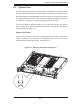
To open the cover, depress the two buttons on the top of the chassis and at the
same time, push the cover away from you until it stops. You can then lift off the
top cover to gain full access to the inside of the server. You must power down the
system before installing or removing CD-ROM, fl oppy or Serial ATA drives. See
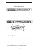
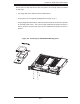
Figure 6-4.
6-4 Drive Bay Installation/Removal
Accessing the Drive Bays
CD-ROM/Serial ATA/Floppy Disk Drives: For installing or removing the CD-ROM,
Serial ATA or fl oppy disk drive, you will need to gain access to the inside of the
1010S-MR by removing the top cover of the chassis. Note: Only a "slim" CD-ROM
and a "slim" fl oppy drive will fi t in the 1010S-MR.
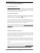
Serial ATA Drive Installation
The SATA drive is located at the front of the chassis, making it easily accessible for
installation and removal. The SATA drive is not hot-swappable, meaning system
power must be turned off before installing or removing.
To install or remove the drive, fi rst power down the system and then remove the top
cover of the chassis. Unscrew the retention screw at the top center of the drive,
then push the drive tray out from the back until you can grasp and pull it out through
the front of the chassis. Remove the drive from the drive tray.
To add a new SATA drive, install a drive into the tray with the printed circuit board
side facing down and with the mounting holes aligned with those in the tray. Secure
the drive to the tray with the four screws. Replace the top cover when fi nished.
See Figure 6-4.