
User Manual
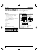

GP2D12/GP2D15
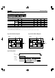
Fig.1 Internal Block Diagram
Fig.2 Internal Block Diagram
■ Electro-optical Characteristics
Parameter
Symbol
Conditions
MIN.
TYP.
MAX.
Unit
Distance measuring range
Output terminal voltage
Difference of output voltage
∆L
0.4
−
−
2.0
33
Vcc −0.3
−
−
10
0.25
− cm
mA
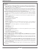
Distance characteristics of output
VO
VOH
∆VO
VOL
VO
ICC
L=80cm
Output voltage at High
Output voltage at Low
Output change at L=80cm to 10cm
L=80cm
0.55
−
0.6
80
V
V
Average Dissipation current
1.75
2.25
24
21
27
50
V
V
cm
(Ta=25°C, V
CC=5V)
GP2D12
GP2D15
GP2D12
GP2D15
*1 Using reflective object : White paper (Made by Kodak Co. Ltd. gray cards R-27 ⋅ white face, reflective ratio ; 90%).
*2 We ship the device after the following adjustment : Output switching distance L=24cm±3cm must be measured by the sensor.
*3 Distance measuring range of the optical sensor system.
*4 Output switching has a hysteresis width. The distance specified by Vo should be the one with which the output L switches to the output H.
*1 *3
*1
*1
*1
*1
*4*2*1
*1
Note) L : Distance to reflective object.
Signal
processing
circuit
Voltage
regulator
Output
circuit
Oscillation
circuit
LED drive
circuit
V
CC
5V
V
o
Analog output
GND
PSD
LED
Distance measuring IC
GP2D12
Signal
processing
circuit
LED drive
circuit
V
CC
5V
V
o
Digital output
GND
PSD
LED
GP2D15
V
CC
12kΩ
Voltage
regulator
Output
circuit
Oscillation
circuit
Distance measuring IC
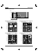
Fig.3 Timing Chart
5.0ms
MAX.
(GP2D12)
7.6ms±1.9ms
TYP.
(GP2D15)
38.3ms±9.6ms
V
O
(Output)
Distance
measuring
operation
First measurment
Second
measurment
nth
measurment
Unstable output First output Second output
nth output
V
CC
(Power supply)
■ Recommended Operating Conditions
Parameter Symbol Rating Unit
V
CC 4.5 to +5.5 V
Operating supply voltage