
Data Sheet
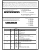
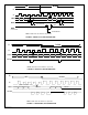

STR. The STR is an 8-bit status register which stores
count related status information.
CY BW CMP IDX CEN PLS U/D S
7 6 5 4 3 2 1 0
7366R-122205-3
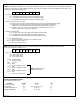
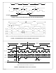
IR. The IR is an 8-bit register that fetches instruction bytes from
the received data stream and executes them to perform such
functions as setting up the operating mode for the chip (load the
MDR) and data transfer among the various registers.
B7 B6 B5 B4 B3 B2 B1 B0
B2 B1 B0 = XXX (Don’t care)
B5 B4 B3 = 000: Select none
= 001: Select MDR0
= 010: Select MDR1
= 011: Select DTR
= 100: Select CNTR
= 101: Select OTR
= 110: Select STR
= 111: Select none
B7 B6 = 00: CLR register
= 01: RD register
= 10: WR register
= 11: LOAD register
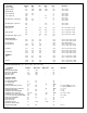
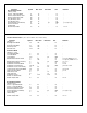
The actions of the four functions, CLR, RD, WR and LOAD are elaborated in Table 1.
TABLE 1
Number of Bytes OP Code Register Operation
MDR0 Clear MDR0 to zero
MRD1 Clear MDR1 to zero
1 CLR DTR None
CNTR Clear CNTR to zero
OTR None
STR Clear STR to zero
MDR0 Output MDR0 serially on TXD (MISO)
MDR1 Output MDR1 serially on TXD (MISO)
2 to 5 RD DTR None
CNTR Transfer CNTR to OTR, then output OTR serially
on TXD (MISO)
OTR Output OTR serially on TXD (MISO)
STR Output STR serially on TXD (MISO)
MDR0 Write serial data at RXD (MOSI) into MDR0
MDR1 Write serial data at RXD (MOSI) into MDR1
2 to 5 WR DTR Write serial data at RXD (MOSI) into DTR
CNTR None
OTR None
STR None
MDR0 None
MDR1 None
1 LOAD DTR None
CNTR Transfer DTR to CNTR in “parallel”
OTR Transfer CNTR to OTR in “parallel”
CNTR. The CNTR is a software configurable 8, 16, 24 or 32-bit up/down counter which counts the up/down pulses resulting from
the quadrature clocks applied at the A and B inputs, or alternatively, in non-quadrature mode, pulses applied at the A input.
By means of IR intructions the CNTR can be cleared, loaded from the DTR or in turn, can be transferred into the OTR.
OTR. The OTR is a software configuration 8, 16, 24 or 32-bit register which can be read back on the MISO output.
Since instantaneous CNTR value is often needed to be read while the CNTR continues to count, the OTR serves as a
convenient dump site for instantaneous CNTR data which can then be read without interfering with the counting process.
CY: Carry (CNTR overflow) latch
BW: Borrow (CNTR underflow) latch
CMP: Compare (CNTR = DTR) latch
IDX: Index latch
CEN: Count enable status: 0: counting disabled,
1: counting enabled
PLS: Power loss indicator latch; set upon power up
U/D: Count direction indicator: 0: count down, 1: count up
S: Sign bit. 1: negative, 0: positive