
Data Sheet

Block diagram and pins description VNH3SP30-E
6/33
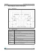
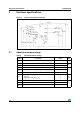
Figure 2. Configuration diagram (top view)
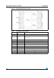
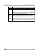
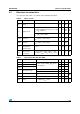
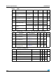
Table 3. Pin definitions and functions
Pin No Symbol Function
1, 25, 30 OUT
A
, Heat Slug3 Source of high side switch A / Drain of low side switch A
2, 4, 7, 9, 12,
14, 17, 22, 24,
29
NC Not connected
3, 13, 23 V
CC
, Heat Slug1 Drain of high side switches and power supply voltage
6EN
A
/DIAG
A
Status of high side and low side switches A; open drain output
5IN
A
Clockwise input
8 PWM PWM input
11 IN
B
Counter clockwise input
10 EN
B
/DIAG
B
Status of high side and low side switches B; open drain output
15, 16, 21 OUT
B
, Heat Slug2 Source of high side switch B / Drain of low side switch B
26, 27, 28 GND
A
Source of low side switch A
(1)
1. GND
A
and GND
B
must be externally connected together.
18, 19, 20 GND
B
Source of low side switch B
(1)