
Data Sheet

VNH3SP30-E Block diagram and pins description
5/33
1 Block diagram and pins description
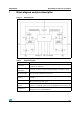
Figure 1. Block diagram
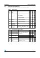
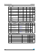
Table 2. Block description
Name Description
Logic control
Allows the turn-on and the turn-off of the high side and the low side switches
according to the truth table
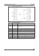
Overvoltage +
undervoltage
Shuts down the device outside the range [5.5V..36V] for the battery voltage
High side and low
side clamp voltage
Protects the high side and the low side switches from the high voltage on the
battery line in all configurations for the motor
High side and low
side driver
Drives the gate of the concerned switch to allow a proper R
DS(on)
for the leg of
the bridge
Linear current limiter
Limits the motor current by reducing the high side switch gate-source voltage
when short-circuit to ground occurs
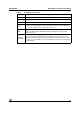
Overtemperature
protection
In case of short-circuit with the increase of the junction’s temperature, shuts
down the concerned high side to prevent its degradation and to protect the die
Fault detection
Signals an abnormal behavior of the switches in the half-bridge A or B by
pulling low the concerned EN
x
/DIAG
x
pin