
Data Sheet

Package and PCB thermal data VNH3SP30-E
26/33
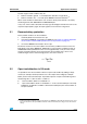
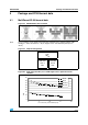
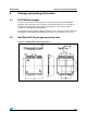
4.1.1 Thermal calculation in clockwise and anti-clockwise operation in
steady-state mode
4.1.2 Thermal resistances definition
(values according to the PCB heatsink area)
R
thHS
= R
thHSA
= R
thHSB
= High Side Chip Thermal Resistance Junction to Ambient (HS
A
or
HS
B
in ON state)
R
thLS
= R
thLSA
= R
thLSB
= Low Side Chip Thermal Resistance Junction to Ambient
R
thHSLS
= R
thHSALSB
= R
thHSBLSA
= Mutual Thermal Resistance Junction to Ambient
between High Side and Low Side Chips
R
thLSLS
= R
thLSALSB
= Mutual Thermal Resistance Junction to Ambient between Low Side
Chips
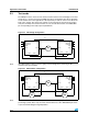
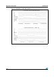
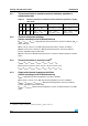
4.1.3 Thermal calculation in transient mode
(b)
T
jHSAB
= Z
thHS
x P
dHSAB
+ Z
thHSLS
x (P
dLSA
+ P
dLSB
) + T
amb
T
jLSA
= Z
thHSLS
x P
dHSAB
+ Z
thLS
x P
dLSA
+ Z
thLSLS
x P
dLSB
+ T
amb
T
jLSB
= Z
thHSLS
x P
dHSAB
+ Z
thLSLS
x P
dLSA
+ Z
thLS
x P
dLSB
+ T
amb
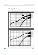
4.1.4 Single pulse thermal impedance definition
(values according to the PCB heatsink area)
Z
thHS
= High Side Chip Thermal Impedance Junction to Ambient
Z
thLS
= Z
thLSA
= Z
thLSB
= Low Side Chip Thermal Impedance Junction to Ambient
Z
thHSLS
= Z
thHSABLSA
= Z
thHSABLSB
= Mutual Thermal Impedance Junction to Ambient
between High Side and Low Side Chips
Z
thLSLS
= Z
thLSALSB
= Mutual Thermal Impedance Junction to Ambient between Low Side
Chips
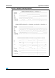
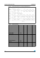
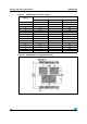
Table 14. Thermal calculation in clockwise and anti-clockwise operation in steady-
state mode
HS
A
HS
B
LS
A
LS
B
T
jHSAB
T
jLSA
T
jLSB
ON OFF OFF ON
P
dHSA
x R
thHS
+ P
dLSB
x R
thHSLS
+ T
amb
P
dHSA
x R
thHSLS
+
P
dLSB
x R
thLSLS
+ T
amb
P
dHSA
x R
thHSLS
+ P
dLSB
x R
thLS
+ T
amb
OFF ON ON OFF
P
dHSB
x R
thHS
+ P
dLSA
x R
thHSLS
+ T
amb
P
dHSB
x R
thHSLS
+
P
dLSA
x R
thLS
+ T
amb
P
dHSB
x R
thHSLS
+ P
dLSA
x R
thLSLS
+ T
amb
b. Calculation is valid in any dynamic operating condition. P
d
values set by user.