
Data Sheet

VNH3SP30-E Package and PCB thermal data
25/33
4 Package and PCB thermal data
4.1 MultiPowerSO-30 thermal data
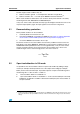
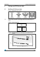
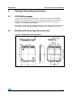
Figure 38. MultiPowerSO-30™ PC board
Note: Layout condition of R
th
and Z
th
measurements (PCB FR4 area = 58mm x 58mm, PCB
thickness = 2mm, Cu thickness = 35m, Copper areas: from minimum pad layout to
16cm
2
).
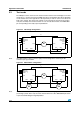
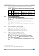
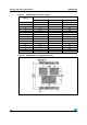
Figure 39. Chipset configuration
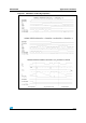
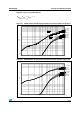
Figure 40. Auto and mutual R
thj-amb
vs PCB copper area in open box free air
condition
HIGH SIDE
CHIP
HS
AB
LOW SIDE
CHIP A
LOW SIDE
CHIP B
LS
A
LS
B
0
5
10
15
20
25
30
35
40
45
0 5 10 15 20
cm
2
of Cu area (refer to PCB layout)
°C/W
RthHS
RthLS
RthHSLS
RthLSLS