
Data Sheet

Application information VNH3SP30-E
22/33
3.3 Test mode
The PWM pin can be used to test the load connection between two half-bridges. In the Test
mode (V
pwm = -2V) the internal power MOS gate drivers are disabled. The INA or INB inputs
can be used to turn on the high side A or B, respectively, in order to connect one side of the
load at V
CC voltage. The check of the voltage on the other side of the load can be used to
verify the continuity of the load connection. In case of load disconnection, the DIAD
X/ENX
pin corresponding to the faulty output is pulled down.
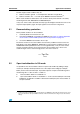
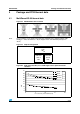
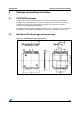
Figure 34. Half-bridge configuration
Note: The VNH3SP30-E can be used as a high power half-bridge driver achieving an On
resistance per leg of 22.5m.
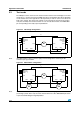
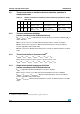
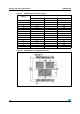
Figure 35. Multi-motors configuration
Note: The VNH3SP30-E can easily be designed in multi-motors driving applications such as seat
positioning systems where only one motor must be driven at a time. DIAG
X
/EN
X
pins allow
to put unused half-bridges in high impedance.
M
OUT
A
OUT
A
OUT
B
OUT
B
V
CC
PWM
DIAG
A
/EN
A
IN
A
DIAG
B
/EN
B
IN
B
GND
B
GND
A
GND
B
GND
A
PWM
DIAG
A
/EN
A
IN
A
DIAG
B
/EN
B
IN
B
M
2
OUT
A
OUT
A
OUT
B
OUT
B
V
CC
PWM
DIAG
A
/EN
A
IN
A
DIAG
B
/EN
B
IN
B
GND
B
GND
A
GND
B
GND
A
PWM
DIAG
A
/EN
A
IN
A
DIAG
B
/EN
B
IN
B
M
1
M
3