
Data Sheet

Application information VNH3SP30-E
20/33
3 Application information
In normal operating conditions the DIAG
X
/EN
X
pin is considered as an input pin by the
device. This pin must be externally pulled high.
PWM pin usage: In all cases, a “0” on the PWM pin will turn off both LS
A
and LS
B
switches.
When PWM rises back to “1”, LS
A
or LS
B
turn on again depending on the input pin state.
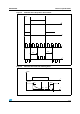
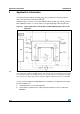
Figure 33. Typical application circuit for DC to 10 kHz PWM operation short circuit
protection
Note: The value of the blocking capacitor (C) depends on the application conditions and defines voltage and
current ripple onto supply line at PWM operation. Stored energy of the motor inductance may fly back
into the blocking capacitor, if the bridge driver goes into tri-state. This causes a hazardous overvoltage
if the capacitor is not big enough. As basic orientation, 500µF per 10A load current is recommended.
In case of a fault condition the DIAG
X
/EN
X
pin is considered as an output pin by the device.
The fault conditions are:
● overtemperature on one or both high sides
● short to battery condition on the output (saturation detection on the low side power
MOSFET)
µC