
Schematic


Table Of Contents
SuperDroid Robots Inc
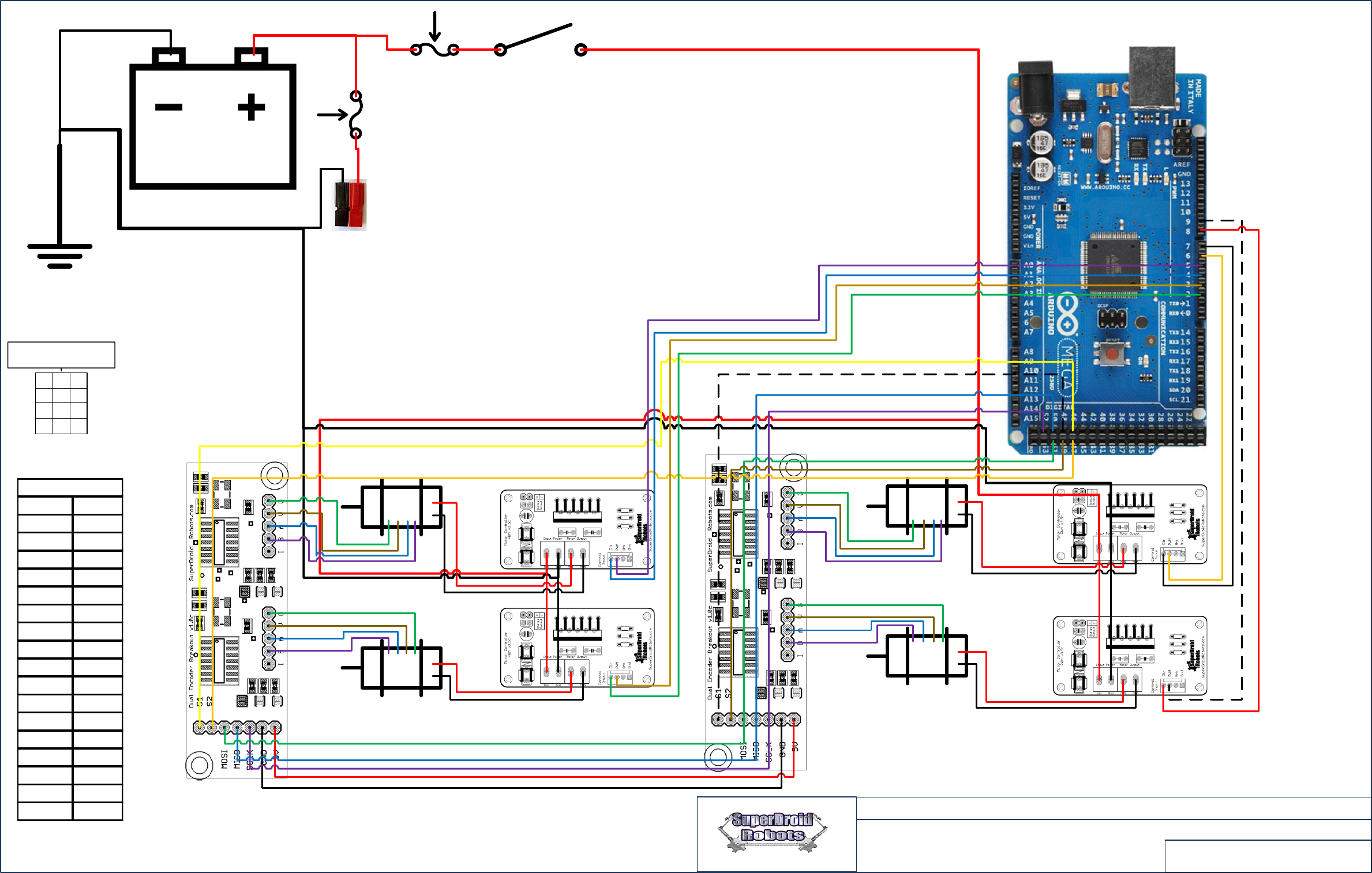
OMNI Wheel Robot Wiring Diagram With PWM
Motor Controller and Encoders
PAGE
2 OF 2
1 2 3
4 65
7
8 9
10 1211
Battery
Fuse
Switch
Fuse
Charge
Port
2 Dir FL
3 PWM FL
4 Dir FR
5 PWM FR
6 PWM RR
7 Dir RR
8 Dir RL
9 PWM RL
11 StrafeRC
12 DriveRC
13 TurnRC
46 (Front)S1
47 (Front)S2
48 (Rear)S1
49 (Rear)S2
50 MISO
51 MOSI
52 SCK
Arduino Pin Out
Front Motors
Rear Motors
RC Receiver
Note In receiver connect:
1. 0 v to pin 3, 6, 9 or 12.
2. 5V to pin 2, 5, 8 or 11.
Arduino Mega
Dual Encoder Breakout Board
Notes:
1. Assembly should be performed by knowledgeable and skilled individual. SuperDroid Robots offers
assembly services if you are not comfortable reading schematics and performing work.
2. Wire gauges depend on load and size of motors.
3. Fuse size depends on load and size of motors.
4. Switch should be rated for at least the same amount of current as the fuse.
5. To charge batteries unplug them and use charger or run parallel wire with plug for charger.
6. Servo pigtail (TE-040-001) typically used. Receiver powered from motor controller (ensure motor
controller rated for receiver).
7. If Battery is 12V you can connect the 2.1mm jack from the arduino to the 12V Bus.
10/31/2016
Front
Right
Front
Left
Rear
Left
Rear
Right
RC receiver Pin out