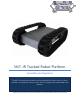
MLT-JR Tracked Robot Platform Assembly and Operation The MLT-JR tracked robot platform and is equipped with 32mm motors, a motor controller, and Spektrum remote control. This is a rugged and maneuverable robot platform.
MLT-JR Tracked Robot Platform Contents Mechanical Assembly ................................................................................................................................................... 4 Electrical Assembly ..................................................................................................................................................... 12 Operation .......................................................................................................................
MLT-JR Tracked Robot Platform It is always important to use safe practices. Only people with good mechanical and electrical experience should work on the robots. Minors should always be supervised by adults. The aluminum chassis also has many sharp edges and care needs to be taken not to get cut. Sharp edges can be brought down with a metal file. The treaded ATRs have very powerful motors.
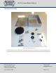
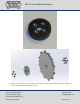
MLT-JR Tracked Robot Platform Mechanical Assembly Parts of the MLT-JR robot kit. 1. Start by pressing the nuts into place on the wheel bearing hubs. There will be 8 nuts and two bearing hubs. Sometimes it helps to use one of the #4 machine screws to hammer the nuts into the counter bored holes. SuperDroid Robots, Inc 224 Technology Park Lane Fuquay Varina, NC 27526 www.SuperDroidRobots.com Contact (919) 557-9162 SDR@SDRobots.
MLT-JR Tracked Robot Platform 2. Mount the bearing hub to the sprocket wheel using the 4-40 X 0.5 flat head machine screws. Tighten the screws until the heads are flush with the wheel. SuperDroid Robots, Inc 224 Technology Park Lane Fuquay Varina, NC 27526 www.SuperDroidRobots.com Contact (919) 557-9162 SDR@SDRobots.
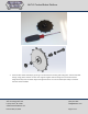
MLT-JR Tracked Robot Platform 3. Finish the idler wheel assembly by pressing in the bronze sleeve bearing and sliding the ¼-20 hex head bolt though, using plastic washers on either side. Tighten together with the flange nut oriented so that the flange faces away from the wheel. Adjust the tightness of the nut until the wheel spins freely around the bolt with minimal wobble. SuperDroid Robots, Inc 224 Technology Park Lane Fuquay Varina, NC 27526 www.SuperDroidRobots.
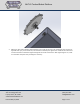
MLT-JR Tracked Robot Platform 4. Mount the idler wheel assembly approximately in the center of the slot in the chassis (this may need to be adjusted when you put the tracks on). The serrated nut should press against the outside of the chassis and a second serrated nut should be tightened against the inside of the chassis. After tightening the nut, make sure the wheel still spins freely and adjust if necessary. SuperDroid Robots, Inc 224 Technology Park Lane Fuquay Varina, NC 27526 www.SuperDroidRobots.
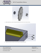
MLT-JR Tracked Robot Platform 5. Bolt the 6mm drive hub to the sprocket wheel with the 4-40 x 0.5” machine screws. 6. Now take the motor and bolt it onto the chassis using the M3 screws. SuperDroid Robots, Inc 224 Technology Park Lane Fuquay Varina, NC 27526 www.SuperDroidRobots.com Contact (919) 557-9162 SDR@SDRobots.
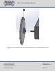
MLT-JR Tracked Robot Platform 7. Slide the drive wheel onto the motor shaft and tighten the set screw onto the flat portion of the motor shaft. SuperDroid Robots, Inc 224 Technology Park Lane Fuquay Varina, NC 27526 www.SuperDroidRobots.com Contact (919) 557-9162 SDR@SDRobots.
MLT-JR Tracked Robot Platform 8. Roll the track onto the wheel. Set one side of the track over the idler wheel and position the teeth inside the tread holes. Line up the other end with the drive wheel and slowly roll the track, idler wheel, and motor wheel (the motor will back drive) and the track will eventually roll itself into position. 9. Now that you have the treads on, roll them to see how they engage the teeth of the sprocket wheels.
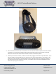
MLT-JR Tracked Robot Platform 10. Mount batteries using battery brackets and hardware provided. Use foam tape on the bracket and underneath the battery to ensure a snug fit. Mark and drill 1/8” holes that match up with the holes in the battery bracket(s). 11. Measure a place on the chassis to mount the switch. The rear plate of the chassis is a good place for it Make sure that it is mounted low enough that it doesn’t interfere with the lid. Drill a ½” hole. 12.
MLT-JR Tracked Robot Platform Electrical Assembly For electrical assembly please follow the provided schematic on our website: Schematics For additional support on wiring, soldering, and crimping, please read the following support pages: Electric Motor Hookup Support Electric Power Hookup Support Soldering Tips Crimping Wires Operation 1. Before powering on the robot make sure it is up on blocks so the wheels can spin freely.
MLT-JR Tracked Robot Platform General Terms 1. SuperDroid Robots, Inc is not responsible for special incidental or consequential damages resulting from any warranty or under any legal theory, including, but not limited to lost profits, downtime, goodwill, damage to, or replacement equipment or property, or any cost of recovering, reprogramming, or reproducing any data stored. ANY LIABILITY SHALL BE LIMITED TO REPLACEMENT OF DEFECTIVE PARTS. SuperDroid Robots, Inc.