
Manual


MLT-42 Kit Assembly Manual
SuperDroid Robots, Inc Contact
224 Technology Park Lane (919) 557-9162
Fuquay Varina, NC 27526 SDR@SDRobots.com
www.SuperDroidRobots.com
Revised: June 22, 2018 Page 7 of 8
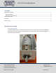
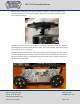
Electrical Assembly
For electrical assembly, please follow the provided schematic on our website:
Sabertooth RC Schematic
When using the LiPo Batteries, the Sabertooth needs to have DIP Switch 3 set in the OFF Position as well.
For additional support on wiring, soldering, and crimping, please read the following support pages:
Electric Motor Hookup Support
Electric Power Hookup Support
Soldering Tips
Crimping Wires
Operation
Before powering on the robot make sure it is up on blocks so the wheels can spin freely. Occasionally
some or all of the wheels start as soon as the motor controller gets power. In this case the settings of the
motor controller need to be changed.
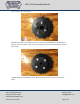
Make sure to use the correct DIP switch settings. If using a Sabertooth motor controller in R/C mode
switch 1 should be DOWN (closest to the number) and all other switches should be UP. If using a different
mode see the manual for the motor controller you are using on Dimension Engineering’s website.
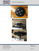
Binding a Spektrum Remote
1. Insert the bind plug into the receiver and power on the robot.
2. While pressing the Bind button, power on the transmitter.
3. Release the Bind button after the receiver’s LED stays illuminated. This indicates the receiver is bound to
the transmitter.
4. Power off the robot and transmitter, remove the bind plug from the receiver.
5. If the wheels are not moving as desired, it may be necessary to swap the Aileron and Elevator plugs or to
reverse the channels on the transmitter. To reverse channels, see the instructions for “Servo Reversing” in
the Spektrum documentation.