LT2-F Assembly Manual Assembly This is an assembly guide to putting the LT2-F Robot together.
LT2-F Assembly Manual Contents Mechanical Assembly ...................................................................................................................................................................... 2 DRIVE INSTALLATION ........................................................................................................................................................................ 2 WHEEL ASSEMBLY ......................................................................................
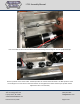
LT2-F Assembly Manual Now to mount the Drive motors. Install the drive motors. Use Loctite and the M5 machine screws and washers provided with the kit. You can leave the bolts a little loose until you get the chains installed and tensioned. SuperDroid Robots, Inc 224 Technology Park Lane Fuquay Varina, NC 27526 www.SuperDroidRobots.com Contact (919) 557-9162 SDR@SDRobots.
LT2-F Assembly Manual Motors installed SuperDroid Robots, Inc 224 Technology Park Lane Fuquay Varina, NC 27526 www.SuperDroidRobots.com Contact (919) 557-9162 SDR@SDRobots.
LT2-F Assembly Manual Mount the tension blocks with the #6 hardware. Get all the screws started but can leave them loose until you install and tension the treads. Slide the rear axle into the tension blocks. Make sure to slide it in so that the middle key slot will line up with the flipper arm motor. SuperDroid Robots, Inc 224 Technology Park Lane Fuquay Varina, NC 27526 www.SuperDroidRobots.com Contact (919) 557-9162 SDR@SDRobots.
LT2-F Assembly Manual Use a lock collar on each side of the blocks to hold the bearings from sliding out. Do not tighten these yet. Put the sprockets on the motor shafts. The #25 sprockets are used for the drive wheels. The #35 sprocket is used for the flipper arm. Put Loctite on the setscrews but do not tighten them down all the way as you will need to adjust them later in the assembly. SuperDroid Robots, Inc 224 Technology Park Lane Fuquay Varina, NC 27526 www.SuperDroidRobots.
LT2-F Assembly Manual Install the back-handle strap. The #10 screws serve two purposes, to tension the treads and also to hold the strap. Get the bolts started in the back of the tension blocks and leave them loose until the tread is installed. SuperDroid Robots, Inc 224 Technology Park Lane Fuquay Varina, NC 27526 www.SuperDroidRobots.com Contact (919) 557-9162 SDR@SDRobots.
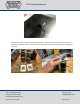
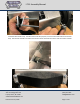
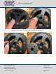
LT2-F Assembly Manual Wheel Assembly Assemble the wheels. You will have two drive wheels with the sprockets mounted, and two idler wheels with no outside teeth or sprocket. Idler wheel assembly. Sandwich the rubber between the two plastic sides. Bolt them together and then press in the center sleeve bearing. Assemble the drive wheels. These use the sprockets and the rubber with the teeth formed into them. Final assembled wheel is on the left.
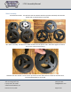
LT2-F Assembly Manual Assemble the wheel using the 2” hardware in the center 4 bolt holes. These go through the wheel and are used to bolt the sprocket on the opposite side of the wheel. SuperDroid Robots, Inc 224 Technology Park Lane Fuquay Varina, NC 27526 www.SuperDroidRobots.com Contact (919) 557-9162 SDR@SDRobots.
LT2-F Assembly Manual Slide a #10 washer down first, then slide the flanged nuts onto the bolts. SuperDroid Robots, Inc 224 Technology Park Lane Fuquay Varina, NC 27526 www.SuperDroidRobots.com Contact (919) 557-9162 SDR@SDRobots.
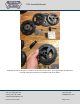
LT2-F Assembly Manual Put the sprocket on top of the flange nuts and then bolt the sprocket down using the #10 locknuts. Press in the sleeve bearing, then turn the wheel over and press in the flanged sleeve bearing on the opposite side of the wheel. SuperDroid Robots, Inc 224 Technology Park Lane Fuquay Varina, NC 27526 www.SuperDroidRobots.com Contact (919) 557-9162 SDR@SDRobots.
LT2-F Assembly Manual Slide the wheel with the sprocket on the front axle. Use a thrust bearing as a spacer. Put another thrust bearing on and then a lock collar to hold everything in place. Wrap the #25 chain around the sprockets and cut the chain to the nearest link. Make sure the motor is slid forward in the slot so you can have plenty of adjustment after it is connected. Install the master-link in the chain as shown. SuperDroid Robots, Inc 224 Technology Park Lane Fuquay Varina, NC 27526 www.
LT2-F Assembly Manual It is very important for everything to be aligned properly. The motor sprocket can be moved in or out to get the chain aligned. The wheel and tread guide should also be aligned. Repeat the previous steps for both sides of the robot. SuperDroid Robots, Inc 224 Technology Park Lane Fuquay Varina, NC 27526 www.SuperDroidRobots.com Contact (919) 557-9162 SDR@SDRobots.
LT2-F Assembly Manual Flipper Assembly Slide the thin bronze washer on the back axle. The put the key in the slot on the shaft. This may require some light filing to ease assembly. SuperDroid Robots, Inc 224 Technology Park Lane Fuquay Varina, NC 27526 www.SuperDroidRobots.com Contact (919) 557-9162 SDR@SDRobots.
LT2-F Assembly Manual Line the flipper arm sprocket up with the motor sprocket. Now is when you should also measure from then end of the shaft to the robot chassis. Adjust the shaft to get each end equal distances on each side. SuperDroid Robots, Inc 224 Technology Park Lane Fuquay Varina, NC 27526 www.SuperDroidRobots.com Contact (919) 557-9162 SDR@SDRobots.
LT2-F Assembly Manual Wrap the #35 chain around the sprockets and cut to length. There is adjustment in the axle slots and in the motor slots. Cut the chain to length and Install the master link. Use two bronze bearings for spacing and slide the idler wheel onto the shaft. Slide a lock collar onto the shaft and then insert the long key into the outside slot. SuperDroid Robots, Inc 224 Technology Park Lane Fuquay Varina, NC 27526 www.SuperDroidRobots.com Contact (919) 557-9162 SDR@SDRobots.
LT2-F Assembly Manual Slide the flipper arm onto the shaft as shown. SuperDroid Robots, Inc 224 Technology Park Lane Fuquay Varina, NC 27526 www.SuperDroidRobots.com Contact (919) 557-9162 SDR@SDRobots.
LT2-F Assembly Manual Insert the 1/4-20 setscrews into the flipper arm on both sides (top and bottom). The opposite side does not have a sprocket, so the spacing will be different. Use a thrust bearing and two lock collars for the spacing. SuperDroid Robots, Inc 224 Technology Park Lane Fuquay Varina, NC 27526 www.SuperDroidRobots.com Contact (919) 557-9162 SDR@SDRobots.
LT2-F Assembly Manual Slide the remaining wheel on the shaft, then another lock collar. Install the remaining key and then flipper arm onto the shaft. Once everything is in place, you may want to adjust the shaft from side to side to make spacing equal, then tighten down all the setscrews on the shaft, including the lock collars on the inside of the robot chassis. SuperDroid Robots, Inc 224 Technology Park Lane Fuquay Varina, NC 27526 www.SuperDroidRobots.com Contact (919) 557-9162 SDR@SDRobots.
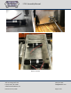
LT2-F Assembly Manual You can now wrap the treads around the wheels. Make sure the tension blocks are slid all the way forward and roll the tracks on each side. The treads are the first thing you have to tension. Make sure the flipper motor bolts are loose, tension the treads and tighten down the #6 bolts that hold the tension blocks. Now tension the flipper arm chain. We find it easiest to slide the motor from the inside of the chassis and tighten the motor bolts down. Tension bolts.
LT2-F Assembly Manual When the tread is tensioned on each side, tighten the 4 screws that hold the tension block. (Here the tread is removed in order to show a better picture. Your tread should be on and you can reach down with a ¼” wrench to tighten the screws.) After each side of the tread is tensioned, you can then tighten the flipper arm motor chain. Slide the motor in the slot until the chain is snug and then tighten down the M5 machine screws that hold the motor into place.
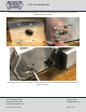
LT2-F Assembly Manual Chain Cutting The easiest way to cut the chain is with a chain breaker tool, illustrated in Error! Reference source not found.. Figure 1 Chain breaker tool Alternatively, clamp the chain in a vise and grind/file the ends of the pins down. Then drive the pin through the chain. Refer to Error! Reference source not found., Error! Reference source not found., and Error! Reference source not found..
LT2-F Assembly Manual Figure 3: Chain grinding/breaking Figure 4: Chain Link removal SuperDroid Robots, Inc 224 Technology Park Lane Fuquay Varina, NC 27526 www.SuperDroidRobots.com Contact (919) 557-9162 SDR@SDRobots.
LT2-F Assembly Manual Install the master link as shown in Error! Reference source not found.. Figure 5: Master Link Installation Electrical Assembly For electrical assembly, please follow the provided schematic on our website: Sabertooth RC Schematic Roboteq RC Schematic Motor Wiring When using the LiPo Batteries, the Sabertooth needs to have DIP Switch 3 set in the OFF Position as well.
LT2-F Assembly Manual Operation Before powering on the robot make sure it is up on blocks so the wheels can spin freely. Occasionally some or all of the wheels start as soon as the motor controller gets power. In this case the settings of the motor controller need to be changed. Make sure to use the correct DIP switch settings. If using a Sabertooth motor controller in R/C mode switch 1 should be DOWN (closest to the number) and all other switches should be UP.