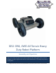
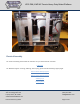
IG52-DB4, 4WD All Terrain Heavy Duty Robot Platform Assembly and Operation This is our Heavy Duty All-Terrain Robot platform with 52mm gear motors, built to navigate through rough terrain and over small obstructions. This heavy duty robot is configurable.
IG52-DB4, 4WD All Terrain Heavy Duty Robot Platform Contents Mechanical Assembly ................................................................................................................................................... 3 Electrical Assembly ....................................................................................................................................................... 9 Operation ................................................................................................
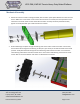
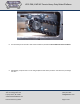
IG52-DB4, 4WD All Terrain Heavy Duty Robot Platform Mechanical Assembly 1. Mount the motors as shown in the figure below, with the motor spacer plate between the motor and the chassis. Make sure to use Loctite on the screws. Once the motor is mounted, the small sprockets can be mounted on the motor shaft. The hub should face the motor and they should be pushed all the way against the inside plate with just a small clearance for rotation. 2.
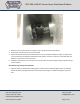
IG52-DB4, 4WD All Terrain Heavy Duty Robot Platform 3. Measure, cut, and install the chain using the chain cutting instructions listed below. 4. At this point, the side slot covers can be mounted. 5. Mount the batteries with the provided hardware. Foam is included if needed for a tight fit. Simply stick it to the underside of the battery bracket before bolting down. The foam can also be used underneath the batteries to space them up over the weld. 6.
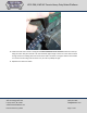
IG52-DB4, 4WD All Terrain Heavy Duty Robot Platform 8. The easiest way to cut the chain is with a chain breaker tool, illustrated in Error! Reference source not found.. 9. Alternatively, clamp the chain in a vise and grind/file the ends of the pins down. Then drive the pin through the chain. SuperDroid Robots, Inc 224 Technology Park Lane Fuquay Varina, NC 27526 www.SuperDroidRobots.com Contact (919) 557-9162 SDR@SDRobots.
IG52-DB4, 4WD All Terrain Heavy Duty Robot Platform SuperDroid Robots, Inc 224 Technology Park Lane Fuquay Varina, NC 27526 www.SuperDroidRobots.com Contact (919) 557-9162 SDR@SDRobots.
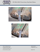
IG52-DB4, 4WD All Terrain Heavy Duty Robot Platform 10. Install the master link as shown in the figure belowError! Reference source not found. and tension chain by s liding the motor away from the axle. The chain should be tight enough so there isn’t much slack but loose enough so that it isn’t adding extra strain on the motor shaft. Listen when running the robot to notice if there is an uneven sound coming from the motor. If so, the chain is probably too tight. 11. Repeat for the other four wheels.
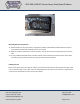
IG52-DB4, 4WD All Terrain Heavy Duty Robot Platform Mounting Electrical Components 12. Mount batteries on top of the chassis using battery brackets and hardware provided. Use foam tape on the bracket and underneath the battery to ensure a snug fit. 13. Measure a place on the chassis to mount the switch. The top of the chassis is a good place for it. Drill a ½” hole. 14. If using a Sabertooth 2x25A motor controller it will fit inside of the chassis with the motors.
IG52-DB4, 4WD All Terrain Heavy Duty Robot Platform Electrical Assembly For electrical assembly please follow the schematic for your selected motor controller: Schematics For additional support on wiring, soldering, and crimping, please read the following support pages: Electric Motor Hookup Support Electric Power Hookup Support Soldering Tips Crimping Wires SuperDroid Robots, Inc 224 Technology Park Lane Fuquay Varina, NC 27526 www.SuperDroidRobots.com Contact (919) 557-9162 SDR@SDRobots.
IG52-DB4, 4WD All Terrain Heavy Duty Robot Platform Operation 1. Before powering on the robot make sure it is up on blocks so the wheels can spin freely. Occasionally some or all of the wheels start as soon as the motor controller gets power. In this case the settings of the motor controller need to be changed. 2. Make sure to use the correct DIP switch settings. If using a Sabertooth motor controller in R/C mode switch 1 should be DOWN (closest to the number) and all other switches should be UP.