
Operation Instructions


Page 9 of 18 Revision Date: February 20, 2007
SuperDroid Robots Inc
http://www.SuperDroidRobots.Com
Assembly of TTL Driver with Status LEDs:
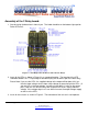
1. Start by laying the board out in front of you. The Label should be on the bottom right topside.
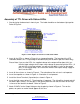
Refer to Figure 4.
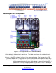
Figure 4: TTL High Current Driver with Status LEDs
2. Insert all the LEDs as shown in Figure 4 in a staggered location. The long leg of the LED
should be towards the TTL Input edge of the board (they will not work if put in the other way).
Please Note: If you use the LEDs, the supplied voltage to the output will be about 10% less
than the Input voltage since it drops some voltage to ground to light the LEDs. (If
you put 12V as the input voltage, you will only get about 11 volts on the output
pins.) If the voltage drop is an issue either increase the output voltage supply or
don’t use the LEDs.
3. Insert all the resistors as shown in Figure 4. The orientation of the resistor is not important.
4. Insert the capacitor as shown in Figure 4. Orientation is not important.
5. Install the Screw Terminals (if provided) as shown in Figure 4.
6. Insert the high current driver IC. The orientation is important. The chip will be shorted and will
not work if put in wrong. Pin one goes in the square pad hole such that the notch on the chip
is closest to the label on the board. Refer to Figure 4.
7. Attach 5-50VDC to the Output Voltage using the polarity shown in Figure 4. Turn on the
power, no sparks or smoke should appear at this time.