
Operation Instructions


Page 8 of 18 Revision Date: February 20, 2007
SuperDroid Robots Inc
http://www.SuperDroidRobots.Com
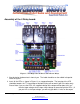
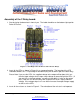
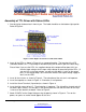
6. Insert the high current driver IC. The orientation is important. The chip will be shorted and will
not work if put in wrong. Pin one goes in the square pad hole such that the notch on the chip
is closest to the label on the board. Refer to Figure 3.
7. Attach either 12VDC or 5VDC to the Output Voltage using the polarity shown in Figure 3. Turn
on the power, no sparks or smoke should appear at this time.
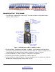
8. Attach your TTL lines from a PIC/+5VDC signal to the Input locations. If you want 1 TTL signal
to dive multiple channels, just install jumpers between the inputs.
9. Attach the Ground for the PIC/+5VDC signal to the input voltage Ground location.
10. Send TTL signals (+5V). The Relay will pull in if you are hooked to channel 7. Channels 1-6
will measure ~90% of the output voltage between the grounded output channel to the +V for
the output voltage supply.