
Operation Instructions

Page 7 of 18 Revision Date: February 20, 2007
SuperDroid Robots Inc
http://www.SuperDroidRobots.Com
Assembly of the 1 Relay board:
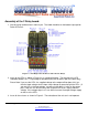
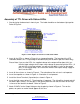
1. Start by laying the board out in front of you. The Label should be on the bottom middle
topside. Refer to Figure 3.
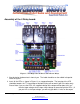
Figure 3: TTL High Current Driver with 1 Power Relay
2. Insert the Diode. Orientation of the Diode is important. It will short the circuit if put in the
wrong way. The lead that comes out of the side of the diode with a line on it should go in the
square pad hole (face towards the left edge of the board as shown in Figure 3).
3. Insert the capacitor as shown in Figure 3. Orientation is not important.
4. Install the Screw Terminals (if provided) as shown in Figure 3.
5. Insert the Relay as shown in Figure 3. Push the relay down so it’s all flat and start soldering
the terminals, checking to make sure the relay stay flat.