
Operation Instructions

Page 2 of 18 Revision Date: February 20, 2007
SuperDroid Robots Inc
http://www.SuperDroidRobots.Com
TTL High Current Driver and RC Switches Assembly
Instructions
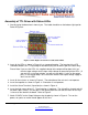
TTL logic outputs from the OOPic or basic stamp, PIC, etc do not have the capacity to drive much
more than an LED. These boards allow you to easily drive higher current devices. It will drive up to
50V and 2 watts of power (1 watt per channel, but the channels can be paralleled for over 1 watt).
The circuit can handle about 500mA continuously. The circuit also has inductive load transient
suppression, which occurs when driving such things as coils on relays.
SuperDroid Robots has four types of TTL High Current Drivers. They all have seven channels of
input and output. Some versions have status LEDs, which will light with the TTL (+5VDC) logic input.
The driver boards with relays are rated at 10A@120VAC per relay. An external power source must be
plugged into the board that drives the loads. If you use the relays, then the supply needs to be either
5VDC or 12VDC otherwise the supply needs to be between 5-50VDC. The 5VDC coils will draw
about 60mA each. The 12VDC coils will draw about 37mA each.
An extension of the TTL High Current Driver is the RC Switches, which use the same relays and
drivers only they are driven by a standard hobby RC signal.
Table of Contents:
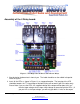
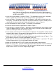
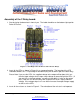
Assembly of the 4 Relay board:.................................................................................................................................................................3
Assembly of the 2 Relay board:.................................................................................................................................................................5
Assembly of the 1 Relay board:.................................................................................................................................................................7
Assembly of TTL Driver with Status LEDs: .............................................................................................................................................9
Assembly of TTL Driver without Status LEDs: ......................................................................................................................................11
Assembly of the DPDT and SPDT Reversing Relay board:....................................................................................................................12
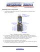
Assembly of the SPDT RC Switch Relay Board:....................................................................................................................................14
Assembly of the DPDT and SPDT Reversing RC Switch Relay board:..................................................................................................16
List of Figures:
Figure 1: TTL High Current Driver with 4 Power Relays........................................................................................................................3
Figure 2: TTL High Current Driver with 2 Power Relays........................................................................................................................5
Figure 3: TTL High Current Driver with 1 Power Relay..........................................................................................................................7
Figure 4: TTL High Current Driver with Status LEDs..............................................................................................................................9
Figure 5: TTL High Current Driver without LEDs..................................................................................................................................11
Figure 6: TTL High Current Driver with DPDT and SPDT Relay.........................................................................................................12
Figure 7: SPDT RC Switch Relay Board................................................................................................................................................14
Figure 8: DPDT and SPDT RC Switch Relay Board..............................................................................................................................16