
Operation Instructions

Page 15 of 18 Revision Date: February 20, 2007
SuperDroid Robots Inc
http://www.SuperDroidRobots.Com
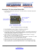
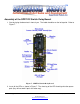
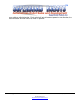
3. Insert all the resistors as shown in Figure 7. Use an ohm meter or refer to the color banding to
determine the values of the resistors. The orientation of the resistor is not important.
4. Insert the Rectifier. Orientation of the rectifier is important. It will short the circuit if put in the
wrong way. The lead that comes out of the side of the rectifier with a line on it should go in the
square pad hole.
5. Insert the capacitor as shown in Figure 7. Orientation is not important.
6. Insert the diode as shown in Figure 7. Orientation of the diode is important. It will short the
circuit if put in the wrong way. The lead that comes out of the side of the diode with a line on it
should go in the square pad hole.
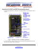
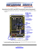
7. Insert the transistor Figure 7. Orientation is important. There is a small tab on the transistor, it
should be oriented as shown in Figure 7 (pointing toward the upper right).
8. Insert the 8 pin IC socket. The orientation is important. The notch should be towards the
capacitor so pin one is in the square hole.
9. Install the Screw Terminals (if provided) as shown in Figure 7.
10. Insert the Relay as shown in Figure 7.
11. Insert the 8 pin preprogrammed. The orientation is important. The notch should be lined up
with the notch on the previously installed IC socket. There is a dot on the IC, its pin one.
12. Attach the RC signal, ground and 5V to the board. You can power this board from the RC
receiver if desired, although a regulated 5V source is best. If the RC receiver is being power
from a non regulated source, such as a battery pack care must be taken. Most NiCad or NiMH
will only output 4.8V, which will work fine. If using 4 alkaline batteries, your voltage will likely
be above 5V, and the board will not work. This can be solved by using the supplied resistors.
The resistor should be put between the supply voltage line (the red/orange line) and the 5V
terminal input on the board. The list below shows the acceptable voltage ranges with and
without resistors.
• 3.2V to 5.1 V, no resistor
• 4.5 to 4.9V, 47 ohm resistor
• 5.9 to 6.7V, 100 ohm resistor
13. When the board is 1
st
powered the red and yellow LEDs will blink back and forth for about a
second. If a RC signal is not present the yellow light will blink fast. If the RC signal is in
neutral position the yellow light will be solid. When the RC signal is ~1/3 up or down, the red
LED will light and the relay will pull in.