
Operation Instructions


Page 11 of 18 Revision Date: February 20, 2007
SuperDroid Robots Inc
http://www.SuperDroidRobots.Com
Assembly of TTL Driver without Status LEDs:
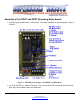
1. Start by laying the board out in front of you. The Label should be on the bottom right topside.
Refer to Figure 5.
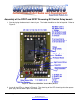
Figure 5: TTL High Current Driver without LEDs
2. Insert the capacitor as shown in Figure 5. Orientation is not important.
3. Install the Screw Terminals (if provided) as shown in Figure 5.
4. Insert the high current driver IC. The orientation is important. The chip will be shorted and will
not work if put in wrong. Pin one goes in the square pad hole such that the notch on the chip
is closest to the label on the board. Refer to Figure 5.
5. Attach 5-50VDC to the Output Voltage using the polarity shown in Figure 5. Turn on the
power, no sparks or smoke should appear at this time.
6. Attach your TTL lines from a PIC/+5VDC signal to the Input locations. If you want 5 TTL signal
to dive multiple channels, just install jumpers between the inputs.
7. Attach the Ground for the PIC/+5VDC signal to the input voltage Ground location.
8. Send TTL signals (+5V). The LED should light and channels 1-7 will measure ~90% of the
output voltage between the grounded output channel to the +V for the output voltage supply.