
Operation Instructions


Page 10 of 18 Revision Date: February 20, 2007
SuperDroid Robots Inc
http://www.SuperDroidRobots.Com
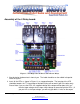
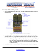
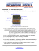
8. Attach your TTL lines from a PIC/+5VDC signal to the Input locations. If you want 1 TTL signal
to dive multiple channels, just install jumpers between the inputs.
9. Attach the Ground for the PIC/+5VDC signal to the input voltage Ground location.
10. Send TTL signals (+5V). The LED should light and channels 1-7 will measure ~90% of the
output voltage between the grounded output channel to the +V for the output voltage supply.