
User's Manual


2-18
X6DH3-G2/X6DHi-G2 User's Manual
LAN1
®
JLAN1
S
UPER X6DH3-G2
LAN2
DIMM 2A
DIM
M 2B
DIMM 3A
DIMM 3
B
DIMM 4A
DIM
M 4B
DIMM 1B
DIMM 1A
12V 8-pin
PWR
JF
1
FP Control
JOH
IPMI
ID
E
2
Floppy
BIOS
Fan4
SMB
PCI-X100 MHz
PCI-X 100 MH
z
Z
CR
(G
reen Slot
)
PCI-X 133 MHz
Battery
JPL1
PCI-
E
X8
VGA
COM1
USB
0
/1
KB/MS
F
an6
F
an5
ATX PWR
12V
4-P
in
PWR
Parrallel
Port
24-Pin
F
a
n7
JPW1
F
an8
C
PU
1
S I/
O
PSF
Fan3
ID
E
1
P
C
I-3
3 MHz
US
B2/
3
I
CH
JPG1
J
WD
Slot1
Slot2
Slot3
Slo
t4
Slot5
Slo
t6
P
C
I-
E
X8
GLAN
CT
RL
6300ES
B
Bu
zze
r
PXH
JBT1
I-SATA1
GLAN
CTRL
JPL2
JL1
JPS
1
SAS
CTRL
Fan2
Fan1
JAR
J3P
C
PU
2
E
7520
Bank1
Bank2
Bank3
Bank4
WOL
SEPC
COM2
SMB PS
JWO
R
JS1
0
V
G
A
C
T
RL
JD1
JI
2
C2
I-S
ATA0
DS5
DS6
DS7
DS8
DS1
DS2
DS3
DS4
SAS4-7
SAS0-3
JSM1
JS9
JP9
J
1D1
J32
J38
J
33
J
14
J
7
J
LAN1
JLAN2
JI
2
C1
J31
JSM2
JP1
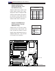
Wake-On-Ring
The Wake-On-Ring header is desig-
nated JWOR.This function allows your
computer to receive and "awakened"
by an incoming call to the modem
when in suspend state. See the table
on the right for pin defi nitions. You
must have a Wake-On-Ring card and
cable to use this feature.
Wake-On-LAN
The Wake-On-LAN header is desig-
nated WOL. See the table on the right
for pin defi nitions. You must enable
the LAN Wake-Up setting in BIOS to
use this feature. You must also have
a LAN card with a Wake-on-LAN con-
nector and cable.
WOR
WOL
Wake-On-Ring
Pin Defi nitions
(JWOR)
Pin# Defi nition
1 Ground (Black)
2 Wake-up
Wake-On-LAN
Pin Defi nitions
(JWOL)
Pin# Defi nition
1 +5V Standby
2 Ground
3 Wake-up