Supermicro Switch Web GUI Quick Configuration Guide Switch Web GUI Quick Configuration Guide for SSE-G48-TG4 SSE-G24-TG4 SSE-X24S SSE-X24SR SSE-X3348S SSE-X3348SR SSE-X3348T SSE-X3348TR SBM-GEM-X2C SBM-GEM-X2C+ SBM-GEM-X3S+ SBM-XEM-X10SM Release: 1.
Supermicro Switch Web GUI Quick Configuration Guide Release: 1.
Supermicro Switch Web GUI Quick Configuration Guide The information in this User’s Manual has been carefully reviewed and is believed to be accurate. The vendor assumes no responsibility for any inaccuracies that may be contained in this document, makes no commitment to update or to keep current the information in this manual, or to notify any person or organization of the updates. Please Note: For the most up-to-date version of this manual, please see our web site at www.supermicro.com.
Supermicro Switch Web GUI Quick Configuration Guide Contents 1 2 Introduction ................................................................................................................. 5 Basic Configurations................................................................................................... 6 2.1 Login Page .......................................................................................................... 6 2.2 Home page ........................................................
Supermicro Switch Web GUI Quick Configuration Guide 1 Introduction This document is designed to provide Supermicro switch users with the information required to configure the basic functionalities on the switch through its Web graphical user interface (GUI). Supermicro Switch products can be configured through Web browsers like Internet Explorer or Mozilla Firefox. To manage a switch through a web browser, type in the management IP address in the web browser address bar.
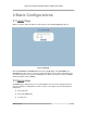
Supermicro Switch Web GUI Quick Configuration Guide 2 Basic Configurations 2.1 Login Page When you type the switch IP address into the browser, the following Login page appears. Fig 1: Login page Enter the User Name and Password and click on the Login button. This User Name and Password are both used for accessing the switch through the web for switch configuration. The user name and password entered are validated by the switch. The default user name is ADMIN and the default password is ADMIN. 2.
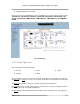
Supermicro Switch Web GUI Quick Configuration Guide Middle Configuration Links Table Except for the Page Top LED Display section, the Home page is same for all the switch products SSE-G48-TG4, SSE-G24-TG4, SSE-X24S, SSE-X24SR, SSE-X3348S, SSE-X3348SR, SSEX3348T, SSE-X3348TR, SBM-GEM-X2C, SBM-GEM-X2C+, SBM-GEM-X3S+ and SBM-XEMX10SM. Fig 2: Home Page 2.2.
Supermicro Switch Web GUI Quick Configuration Guide The Logout link provides a means of signing out of the management web application. It returns to the login screen requesting a user name and password for login. 2.2.2 Page Top LED Display This part of the screen displays the port status of the switch. It displays Speed and Link status for every port. Since the number of ports is different in each of the switches, this displays a different number of ports for each type of switch.
Supermicro Switch Web GUI Quick Configuration Guide 2.2.3 Left Side Tree The Left Side Tree display on the left side of the page provides quick access to configuration pages. This tree is organized based on the features supported in the switch. The main features are categorized as follows: System Management – System based configurations Layer 2 Management – Layer 2 Protocols including VLAN, RSTP, MSTP … Layer 3 Management – Layer 3 Protocols including – IP, RIP, OSPF ….
Supermicro Switch Web GUI Quick Configuration Guide 2.3 Management IP Address Note: The default management IP address for all Supermicro switch products is: 192.168.100.102. Switch Management IP Interface SSE-G24-TG4 The management IP address is configured for VLAN 1. All front 1-Gb ports and back 10Gb ports are configured as untagged member ports of VLAN 1 by default.
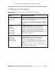
Supermicro Switch Web GUI Quick Configuration Guide 2.3.1 Changing the Management IP Address & Gateway The management IP address and default gateway can be configured in the System Mgmt Management IP page. Fig 3: Management IP Page IP Address Mode – For a static IP addresses use the Manual mode. To get an IP address through DHCP, use the Dynamic mode. IP Address – Use this setting to configure the IP address for static manual mode.
Supermicro Switch Web GUI Quick Configuration Guide 2.4 User Accounts The default administrative user name for all Supermicro switches is ADMIN and the password for all these switches is also ADMIN. The password for this ADMIN user can be changed in the page System Mgmt Management Security Local Users. New users can be created with different privilege levels. Fifteen is the highest privilege – it equals the ADMIN user.
Supermicro Switch Web GUI Quick Configuration Guide 2.5 Interface MTU and Jumbo Frames The interface MTU can be changed in Layer2 Mgmt Port Manager Basic Settings page. The default MTU is 1500 bytes. The maximum MTU supported is 9202. The Supermicro switch MTU refers only to the layer 2 payload size. Hence the MTU of 9202 means a total “in-wire” MTU of 9220 (14 bytes Ethernet Header plus 4 bytes FCS are added).
Supermicro Switch Web GUI Quick Configuration Guide Interfaces can be given a description or name in text. This helps users to identify or remember the interface connections with other components on the network. The interface description can be configured in Layer2 Mgmt Port Manager Basic Settings page. Fig 6: Interface Description Page Release: 1.
Supermicro Switch Web GUI Quick Configuration Guide 2.7 Stacking The SSE-G24-TG4 and SSE-G48-TG4 switches support stacking of up to 16 switches. SBMGEM-X2C, SBM-GEM-X2C+ support stacking of up to 8 switches. Stacking can be configured from the System Mgmt Stack Stack Settings page. Fig 7: Stacking Page In the Ports field, list the stacking ports as comma separated without space characters. Stacking ports are named as xg1, xg2, xg3 and xg4.
Supermicro Switch Web GUI Quick Configuration Guide Note: 1. Do not use the same switch ID for multiple switches on the stack. 2. All switches in the stack can only be configured through the master switch. 3. Make sure all stacked switches run the same version of firmware! 4. Only the same switch models can be stacked together. For example, the SSE-G24-TG4 switch can only be stacked with other SSE-G24-TG4 switches. 5. Use the same stacking ports configuration across all the switches in stack.
Supermicro Switch Web GUI Quick Configuration Guide In the Upstream Interfaces field and Downstream Interfaces fields, list the ports as comma separated without space characters. For example to choose ports gi0/1 to gi0/5 and gi0/10 as downstream ports, configure the Downstream Interfaces field as “gi0/1-5,gi0/10”.
Supermicro Switch Web GUI Quick Configuration Guide 2.9 Saving Configurations Switch configurations can be saved on the System Mgmt File Management page. You can save a currently running switch configuration in one of three ways. Save Startup Config – This option saves the current running configuration in local flash with the file name configured as “startup configuration” file. This configuration will be loaded automatically every time the switch reboots.
Supermicro Switch Web GUI Quick Configuration Guide 2.10 Upgrading Firmware Switch firmware can be upgraded in the System Mgmt Firmware Upgrade page. Flash Area – The default selection is Normal to upgrade firmware in normal flash area. To upgrade firmware in the fallback flash area, choose Flash Area as the Fallback. File Name – Use the Browse button to select the switch firmware from local computer.
Supermicro Switch Web GUI Quick Configuration Guide 2.11 Resetting to Factory Defaults Supermicro switches can be reset to factory defaults in the System Mgmt System Settings page. This page has a button that you can press to allow a “Reset To Factory Defaults”. This will clear all information about switch configurations and local user accounts. Make sure to have all necessary configurations backed up before doing “Reset To Factory Defaults” in external computers.
Supermicro Switch Web GUI Quick Configuration Guide 3 VLAN Configurations The SSE-G24-TG4, SSE-G48-TG4, SBM-GEM-X2C, SBM-GEM-X2C+ and SBM-GEM-X3S+ switches support 1024 static VLANs. The SSE-X24S, SSE-X24SR, SSE-X3348S, SSE-X3348SR, SSE-X3348T, SSE-X3348TR and SBM-XEM-X10SM switches support 4K static VLANs. VLANs can be configured in Layer2 Mgmt VLAN Static VLANs page.
Supermicro Switch Web GUI Quick Configuration Guide Member Ports – Provide all the member ports of this VLAN including tagged and untagged member ports. Untagged Ports – These are the member ports that need to be configured as untagged ports. If all the ports of this VLAN are untagged, member ports and untagged ports will be same. Forbidden Ports – This is a list of any ports that need to forbidden from this VLAN.
Supermicro Switch Web GUI Quick Configuration Guide 4 Link Aggregation (LA) Link Aggregation (LA) is a method of combining multiple parallel physical connections into a single logical connection(trunk), thus allowing increased bandwidth for a particular network path beyond what a single connection could sustain. By taking multiple LAN connections and treating them as a unified, aggregated link, practical benefits in many applications can be achieved.
Supermicro Switch Web GUI Quick Configuration Guide Fig 13: LA Status Page 4.2 Creating a Port Channel A port channel can be created in the Layer2 Mgmt LA Interface Settings page. Release: 1.
Supermicro Switch Web GUI Quick Configuration Guide Fig 14: Port Channel Page To create any port channel, enter the Port Channel ID in the page-top dialog box and click Add. Release: 1.
Supermicro Switch Web GUI Quick Configuration Guide 4.3 Associating a Port Channel with Ports Once a port channel is created in the port channel page, it can be associated with the required physical ports. This can be done in the Layer2 Mgmt LA Port Settings page. Configure Port Channel and Mode for the required physical ports. Use the mode “ON” for static port channels. Use the mode as “ACTIVE” or “PASSIVE” for LACP port channels.
Supermicro Switch Web GUI Quick Configuration Guide 4.4 Configuring Port Channel Parameters Once a port channel is created and associated with the required ports, you can configure the port channel parameters. If necessary configure the MTU of the port channel in the Port Channel page (Fig 14). The default value is 1500. If necessary configure the name or description of the port channel in the Port Channel page (Fig 14). Make the port channel Admin Status as “UP” in the Port Channel page (Fig 14).