SUPER ® SUPERSERVER 6016T-6RFT+ SUPERSERVER 6016T-6RF+ USER’S MANUAL 1.
The information in this User’s Manual has been carefully reviewed and is believed to be accurate. The vendor assumes no responsibility for any inaccuracies that may be contained in this document, makes no commitment to update or to keep current the information in this manual, or to notify any person or organization of the updates. Please Note: For the most up-to-date version of this manual, please see our web site at www.supermicro.com. Super Micro Computer, Inc.
Preface Preface About This Manual This manual is written for professional system integrators and PC technicians. It provides information for the installation and use of the SuperServer 6016T6RFT+/6016T-6RF+. Installation and maintenance should be performed by experienced technicians only.
SUPERSERVER 6016T-6RFT+/6016T-6RF+ User's Manual Chapter 5: Advanced Serverboard Setup Chapter 5 provides detailed information on the X8DTU-6TF+/X8DTU-6F+ serverboard, including the locations and functions of connections, headers and jumpers. Refer to this chapter when adding or removing processors or main memory and when reconfiguring the serverboard. Chapter 6: Advanced Chassis Setup Refer to Chapter 6 for detailed information on the SC819TQ-R700U server chassis.
Preface Notes v
SUPERSERVER 6016T-6RFT+/6016T-6RF+ User's Manual Table of Contents Chapter 1 Introduction 1-1 Overview ......................................................................................................... 1-1 1-2 Serverboard Features ..................................................................................... 1-2 Processors ...................................................................................................... 1-2 Memory .......................................................
Table of Contents Installing the Server into a Telco Rack ........................................................... 2-6 2-6 Checking the Serverboard Setup .................................................................... 2-8 Chapter 3 System Interface 3-1 Overview ......................................................................................................... 3-1 3-2 Control Panel Buttons .....................................................................................
SUPERSERVER 6016T-6RFT+/6016T-6RF+ User's Manual X8DTU-6TF+/X8DTU-6F+ Quick Reference ................................................. 5-14 5-8 Connector Definitions .................................................................................... 5-15 5-9 Jumper Settings ............................................................................................ 5-23 5-10 Onboard Indicators........................................................................................
Chapter 1: Introduction Chapter 1 Introduction 1-1 Overview The SuperServer 6016T-6RFT+/6016T-6RF+ is a comprised of two main subsystems: the SC819TQ-R700U 1U server chassis and the X8DTU-6TF+/X8DTU-6F+ dual processor serverboard. Please refer to our web site for information on operating systems that have been certified for use with the system (www.supermicro.com).
SUPERSERVER 6016T-6RFT+/6016T-6RF+ User's Manual 1-2 Serverboard Features At the heart of the SuperServer 6016T-6RFT+/6016T-6RF+ lies the X8DTU-6TF+/ X8DTU-6F+, a dual processor serverboard based on the Intel® 5520 chipset. Below are the main features of the serverboard. (See Figure 1-1 for a block diagram of the chipset). Processors The X8DTU-6TF+/X8DTU-6F+ supports single or dual Intel® 5500/5600 Series processors in LGA1366 sockets.
Chapter 1: Introduction 10 supported (RAID 5 is supported with Windows OS only). The SATA drives are hot-swappable units. Note: You must have RAID set up to enable the hot-swap capability of the SATA drives. Documentation on RAID setup guidelines can be found on our web site. Rear I/O Ports The color-coded I/O ports include one COM port, a VGA (monitor) port, two USB 2.0 ports, PS/2 mouse and keyboard ports, one dedicated IPMI LAN port and two gigabit Ethernet ports.
SUPERSERVER 6016T-6RFT+/6016T-6RF+ User's Manual PCI Expansion Slots Two riser cards are included. The RSC-R1UU-E8R+ is located on the right side of the chassis and supports one low-profile PCI-E x4 card (in a x8 slot). The RSCR1UU-2E8 is located on the left side of the chassis and supports two PCI-E x8 add-on cards. See our web site for details (http://www.supermicro.com/products/ nfo/UIO.cfm). See section 5-6 of this manual for details.
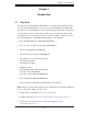
Chapter 1: Introduction Figure 1-1. Intel 5520 + IOH-36D/ICH10R Chipset: System Block Diagram Processor#0 Processor#1 C PORT1 PORT1 Gen2 x4 Gen2 x8 PORT0 PORT 7,8,9,10 PORT 1,2 PORT 3,4 PORT 5,6 F E F QPI QPI Gen2 x16 E DDR3 DIMM B D DDR3 DIMM QPI A DDR3 DIMM DDR3 DIMM DDR3 DIMM B PCI-E x16 C PCI-Ex8 in x4 slot PCI-E x8 in x16 slot DDR3 DIMM Note: This is a general block diagram. Please see Chapter 5 for details.
SUPERSERVER 6016T-6RFT+/6016T-6RF+ User's Manual 1-4 Contacting Supermicro Headquarters Address: Super Micro Computer, Inc. 980 Rock Ave. San Jose, CA 95131 U.S.A. Tel: +1 (408) 503-8000 Fax: +1 (408) 503-8008 Email: marketing@supermicro.com (General Information) support@supermicro.com (Technical Support) Web Site: www.supermicro.com Europe Address: Super Micro Computer B.V.
Chapter 2: Server Installation Chapter 2 Server Installation 2-1 Overview This chapter provides a quick setup checklist to get your 6016T-6RFT+/6016T-6RF+ up and running. Following these steps in the order given should enable you to have the system operational within a minimum amount of time. This quick setup assumes that your system has come to you with the processors and memory pre-installed. If your system is not already fully integrated with a serverboard, processors, system memory etc.
SUPERSERVER 6016T-6RFT+/6016T-6RF+ User's Manual installation only in a Restricted Access Location (dedicated equipment rooms, service closets and the like). • This product is not suitable for use with visual display work place devices acccording to §2 of the the German Ordinance for Work with Visual Display Units.
Chapter 2: Server Installation Rack Mounting Considerations Ambient Operating Temperature If installed in a closed or multi-unit rack assembly, the ambient operating temperature of the rack environment may be greater than the ambient temperature of the room. Therefore, consideration should be given to installing the equipment in an environment compatible with the manufacturer’s maximum rated ambient temperature (Tmra).
SUPERSERVER 6016T-6RFT+/6016T-6RF+ User's Manual 2-5 Installing the System into a Rack This section provides information on installing the 6016T-6RFT+/6016T-6RF+ into a rack unit with the rack rails provided. If the system has already been mounted into a rack, you can skip ahead to Sections 2-5 and 2-6. There are a variety of rack units on the market, which may mean the assembly procedure will differ slightly.
Chapter 2: Server Installation Installing the Outer Rails Installing the Outer Rails to the Rack 1. Measure the distance from the front rail to the rear rail of the rack. 2. Attach a short bracket to the front side of the right outer rail and a long bracket to the rear side of the right outer rail. 3. Adjust both the short and long brackets to the proper distance so that the rail can fit snugly into the rack. 4.
SUPERSERVER 6016T-6RFT+/6016T-6RF+ User's Manual Installing the Server into the Rack Installing the Chassis into a Rack (Figure 2-3) 1. Confirm that chassis includes the inner rails and rail extensions . Also, confirm that the outer rails are installed on the rack. 2. Line chassis rails with the front of the rack rails. 3. Slide the chassis rails into the rack rails, keeping the pressure even on both sides (you may have to depress the locking tabs when inserting).
Chapter 2: Server Installation Figure 2-3.
SUPERSERVER 6016T-6RFT+/6016T-6RF+ User's Manual 2-6 Checking the Serverboard Setup After you install the system in the rack, you will need to open the top cover to make sure the serverboard is properly installed and all the connections have been made. Accessing the Inside of the System 1. First, grasp the two handles on either side and pull the system straight out until it locks (you will hear a "click"). 2. Next, press the two buttons on the top of the chassis to release the top cover. 3.
Chapter 2: Server Installation Figure 2-4.
SUPERSERVER 6016T-6RFT+/6016T-6RF+ User's Manual 2-7 Checking the Drive Bay Setup Next, you should check to make sure the peripheral drives and the hard drives and backplane have been properly installed and all connections have been made. Checking the Drives 1. All drives are accessable from the front of the server. The hard disk drives can be installed and removed from the front of the chassis without removing the top chassis cover. 2. A slim DVD-ROM drive should be preinstalled in your server.
Chapter 3: System Interface Chapter 3 System Interface 3-1 Overview There are several LEDs on the control panel as well as others on the hard drive carriers to keep you constantly informed of the overall status of the system as well as the activity and health of specific components. There are also two buttons on the chassis control panel and an on/off switch on the power supply. This chapter explains the meanings of all LED indicators and the appropriate response you may need to take.
SUPERSERVER 6016T-6RFT+/6016T-6RF+ User's Manual 3-3 Control Panel LEDs The control panel located on the front of the SC819TQ chassis has five LEDs. These LEDs provide you with critical information related to different parts of the system. This section explains what each LED indicates when illuminated and any corrective action you may need to take. UID/Overheat/Fan Fail/Power Fail Blue: This LED turns on when either the front or the rear UID button is pushed.
Chapter 3: System Interface Power Indicates power is being supplied to the system's power supply units. This LED should normally be illuminated when the system is operating. 3-4 • • Drive Carrier LEDs Green: Each SAS/SATA drive carrier has a green LED. When illuminated, this green LED indicates drive activity. A connection to the SAS/SATA backplane enables this LED to blink on and off when that particular drive is being accessed.
SUPERSERVER 6016T-6RFT+/6016T-6RF+ User's Manual Notes 3-4
Chapter 4: Warning Statements for AC Systems Chapter 4 Standardized Warning Statements for AC Systems 4-1 About Standardized Warning Statements The following statements are industry standard warnings, provided to warn the user of situations which have the potential for bodily injury. Should you have questions or experience difficulty, contact Supermicro's Technical Support department for assistance. Only certified technicians should attempt to install or configure components.
SUPERSERVER 6016T-6RFT+/6016T-6RF+ User's Manual Warnung WICHTIGE SICHERHEITSHINWEISE Dieses Warnsymbol bedeutet Gefahr. Sie befinden sich in einer Situation, die zu Verletzungen führen kann. Machen Sie sich vor der Arbeit mit Geräten mit den Gefahren elektrischer Schaltungen und den üblichen Verfahren zur Vorbeugung vor Unfällen vertraut.
Warning Statements for AC Systems . ﺗﺤﺬﻳﺮ!ﻫﺬﺍ ﺍﻟﺮﻣﺰ ﻳﻌﻨﻲ ﺧﻄﺮ ﺍﻧﻚ ﻓﻲ ﺣﺎﻟﺔ ﻳﻤﻜﻦ ﺃﻥ ﺗﺘﺴﺒﺐ ﻓﻲ ﺍﺻﺎﺑﺔ ﺟﺴﺪﻳﺔ ﻛﻦ ﻋﻠﻰ ﻋﻠﻢ ﺑﺎﻟﻤﺨﺎﻁﺮ ﺍﻟﻨﺎﺟﻤﺔ ﻋﻦ ﺍﻟﺪﻭﺍﺋﺮ،ﻗﺒﻞ ﺃﻥ ﺗﻌﻤﻞ ﻋﻠﻰ ﺃﻱ ﻣﻌﺪﺍﺕ ﺍﻟﻜﻬﺮﺑﺎﺋﻴﺔ ﻭﻛﻦ ﻋﻠﻰ ﺩﺭﺍﻳﺔ ﺑﺎﻟﻤﻤﺎﺭﺳﺎﺕ ﺍﻟﻮﻗﺎﺋﻴﺔ ﻟﻤﻨﻊ ﻭﻗﻮﻉ ﺃﻱ ﺣﻮﺍﺩﺙ ﺍﺳﺘﺨﺪﻡ ﺭﻗﻢ ﺍﻟﺒﻴﺎﻥ ﺍﻟﻤﻨﺼﻮﺹ ﻓﻲ ﻧﻬﺎﻳﺔ ﻛﻞ ﺗﺤﺬﻳﺮ ﻟﻠﻌﺜﻮﺭ ﺗﺮﺟﻤﺘﻬﺎ 안전을 위한 주의사항 경고! 이 경고 기호는 위험이 있음을 알려 줍니다. 작업자의 신체에 부상을 야기 할 수 있는 상태에 있게 됩니다. 모든 장비에 대한 작업을 수행하기 전에 전기회로와 관련된 위험요소들을 확인하시고 사전에 사고를 방지할 수 있도록 표준 작업절차를 준수해 주시기 바랍니다.
SUPERSERVER 6016T-6RFT+/6016T-6RF+ User's Manual Installation Instructions Warning! Read the installation instructions before connecting the system to the power source. 設置手順書 システムを電源に接続する前に、設置手順書をお読み下さい。 警告 将此系统连接电源前,请先阅读安装说明。 警告 將系統與電源連接前,請先閱讀安裝說明。 Warnung Vor dem Anschließen des Systems an die Stromquelle die Installationsanweisungen lesen. ¡Advertencia! Lea las instrucciones de instalación antes de conectar el sistema a la red de alimentación.
Chapter 4: Warning Statements for AC Systems Circuit Breaker Warning! This product relies on the building's installation for short-circuit (overcurrent) protection. Ensure that the protective device is rated not greater than: 250 V, 20 A.
SUPERSERVER 6016T-6RFT+/6016T-6RF+ User's Manual 경고! 이 제품은 전원의 단락(과전류)방지에 대해서 전적으로 건물의 관련 설비에 의존합니다. 보호장치의 정격이 반드시 250V(볼트), 20A(암페어)를 초과하지 않도록 해야 합니다. Waarschuwing Dit product is afhankelijk van de kortsluitbeveiliging (overspanning) van uw electrische installatie. Controleer of het beveiligde aparaat niet groter gedimensioneerd is dan 220V, 20A.
Chapter 4: Warning Statements for AC Systems ¡Advertencia! El sistema debe ser disconnected de todas las fuentes de energía y del cable eléctrico quitado de los módulos de fuente de alimentación antes de tener acceso el interior del chasis para instalar o para quitar componentes de sistema. Attention Le système doit être débranché de toutes les sources de puissance ainsi que de son cordon d'alimentation secteur avant d'accéder à l'intérieur du chassis pour installer ou enlever des composants de systéme.
SUPERSERVER 6016T-6RFT+/6016T-6RF+ User's Manual Equipment Installation Warning! Only trained and qualified personnel should be allowed to install, replace, or service this equipment. 機器の設置 トレーニングを受け認定された人だけがこの装置の設置、交換、 またはサービスを許可 されています。 警告 只有经过培训且具有资格的人员才能进行此设备的安装、更换和维修。 警告 只有經過受訓且具資格人員才可安裝、更換與維修此設備。 Warnung Das Installieren, Ersetzen oder Bedienen dieser Ausrüstung sollte nur geschultem, qualifiziertem Personal gestattet werden.
Chapter 4: Warning Statements for AC Systems Waarschuwing Deze apparatuur mag alleen worden geïnstalleerd, vervangen of hersteld door geschoold en gekwalificeerd personeel. Restricted Area Warning! This unit is intended for installation in restricted access areas. A restricted access area can be accessed only through the use of a special tool, lock and key, or other means of security. (This warning does not apply to workstations).
SUPERSERVER 6016T-6RFT+/6016T-6RF+ User's Manual אזור עם גישה מוגבלת !אזהרה הגישה ניתנת בעזרת.יש להתקין את היחידה באזורים שיש בהם הגבלת גישה .(' מנעול וכד,כלי אבטחה בלבד )מפתח . ﺗﻢ ﺗﺨﺼﻴﺺ ﻫﺬﻩ ﺍﻟﻮﺣﺪﺓ ﻟﺘﺮﻛﻴﺒﻬﺎ ﻓﻲ ﻣﻨﺎﻁﻖ ﻣﺤﻈﻮﺭﺓ ،ﻳﻤﻜﻦ ﺍﻟﻮﺻﻮﻝ ﺇﻟﻰ ﻣﻨﻄﻘﺔ ﻣﺤﻈﻮﺭﺓ ﻓﻘﻂ ﻣﻦ ﺧﻼﻝ ﺍﺳﺘﺨﺪﺍﻡ ﺃﺩﺍﺓ ﺧﺎﺻﺔ ﻗﻔﻞ ﻭﻣﻔﺘﺎﺡ ﺃﻭ ﺃﻱ ﻭﺳﻴﻠﺔ ﺃﺧﺮﻯ ﻟﻼﻷﻣﺎﻥ 경고! 이 장치는 접근이 제한된 구역에 설치하도록 되어있습니다. 특수도구, 잠금 장치 및 키, 또는 기타 보안 수단을 통해서만 접근 제한 구역에 들어갈 수 있습니다.
Chapter 4: Warning Statements for AC Systems Warnung Bei Einsetzen einer falschen Batterie besteht Explosionsgefahr. Ersetzen Sie die Batterie nur durch den gleichen oder vom Hersteller empfohlenen Batterietyp. Entsorgen Sie die benutzten Batterien nach den Anweisungen des Herstellers. Attention Danger d'explosion si la pile n'est pas remplacée correctement. Ne la remplacer que par une pile de type semblable ou équivalent, recommandée par le fabricant.
SUPERSERVER 6016T-6RFT+/6016T-6RF+ User's Manual Redundant Power Supplies Warning! This unit might have more than one power supply connection. All connections must be removed to de-energize the unit. 冗長電源装置 このユニットは複数の電源装置が接続されている場合があります。 ユニットの電源を切るためには、すべての接続を取り外さなければなりません。 警告 此部件连接的电源可能不止一个,必须将所有电源断开才能停止给该部件供电。 警告 此裝置連接的電源可能不只一個,必須切斷所有電源才能停止對該裝置的供電。 Warnung Dieses Gerät kann mehr als eine Stromzufuhr haben.
Chapter 4: Warning Statements for AC Systems .ﻗﺪ ﻳﻜﻮﻥ ﻟﻬﺬﺍ ﺍﻟﺠﻬﺎﺯ ﻋﺪﺓ ﺍﺗﺼﺎﻻﺕ ﺑﻮﺣﺪﺍﺕ ﺍﻣﺪﺍﺩ ﺍﻟﻄﺎﻗﺔ ﻳﺠﺐ ﺇﺯﺍﻟﺔ ﻛﺎﻓﺔ ﺍﻻﺗﺼﺎﻻﺕ ﻟﻌﺰﻝ ﺍﻟﻮﺣﺪﺓ ﻋﻦ ﺍﻟﻜﻬﺮﺑﺎء 경고! 이 장치에는 한 개 이상의 전원 공급 단자가 연결되어 있을 수 있습니다. 이 장치에 전원을 차단하기 위해서는 모든 연결 단자를 제거해야만 합니다. Waarschuwing Deze eenheid kan meer dan één stroomtoevoeraansluiting bevatten. Alle aansluitingen dienen verwijderd te worden om het apparaat stroomloos te maken. Backplane Voltage Warning! Hazardous voltage or energy is present on the backplane when the system is operating.
SUPERSERVER 6016T-6RFT+/6016T-6RF+ User's Manual מתח בפנל האחורי !אזהרה יש להיזהר במהלך.קיימת סכנת מתח בפנל האחורי בזמן תפעול המערכת .העבודה ﻫﻨﺎﻙ ﺧﻄﺮ ﻣﻦ ﺍﻟﺘﻴﺎﺭ ﺍﻟﻜﻬﺮﺑﺎﺋﻲ ﺃﻭﺍﻟﻄﺎﻗﺔ ﺍﻟﻤﻮﺟﻮﺩﺓ ﻋﻠﻰ ﺍﻟﻠﻮﺣﺔ ﻋﻨﺪﻣﺎ ﻳﻜﻮﻥ ﺍﻟﻨﻈﺎﻡ ﻳﻌﻤﻞ ﻛﻦ ﺣﺬﺭﺍ ﻋﻨﺪ ﺧﺪﻣﺔ ﻫﺬﺍ ﺍﻟﺠﻬﺎﺯ 경고! 시스템이 동작 중일 때 후면판 (Backplane)에는 위험한 전압이나 에너지가 발생 합니다. 서비스 작업 시 주의하십시오. Waarschuwing Een gevaarlijke spanning of energie is aanwezig op de backplane wanneer het systeem in gebruik is. Voorzichtigheid is geboden tijdens het onderhoud.
Chapter 4: Warning Statements for AC Systems Attention L'équipement doit être installé conformément aux normes électriques nationales et locales. תיאום חוקי החשמל הארצי !אזהרה .התקנת הציוד חייבת להיות תואמת לחוקי החשמל המקומיים והארציים ﺗﺮﻛﻴﺐ ﺍﻟﻤﻌﺪﺍﺕ ﺍﻟﻜﻬﺮﺑﺎﺋﻴﺔ ﻳﺠﺐ ﺃﻥ ﻳﻤﺘﺜﻞ ﻟﻠﻘﻮﺍﻧﻴﻦ ﺍﻟﻤﺤﻠﻴﺔ ﻭﺍﻟﻮﻁﻨﻴﺔ ﺍﻟﻤﺘﻌﻠﻘﺔ ﺑﺎﻟﻜﻬﺮﺑﺎء 경고! 현 지역 및 국가의 전기 규정에 따라 장비를 설치해야 합니다. Waarschuwing Bij installatie van de apparatuur moet worden voldaan aan de lokale en nationale elektriciteitsvoorschriften.
SUPERSERVER 6016T-6RFT+/6016T-6RF+ User's Manual ¡Advertencia! Al deshacerse por completo de este producto debe seguir todas las leyes y reglamentos nacionales. Attention La mise au rebut ou le recyclage de ce produit sont généralement soumis à des lois et/ou directives de respect de l'environnement. Renseignez-vous auprès de l'organisme compétent. סילוק המוצר !אזהרה .
Chapter 4: Warning Statements for AC Systems 警告 當您從機架移除風扇裝置,風扇可能仍在轉動。小心不要將手指、螺絲起子和其他 物品太靠近風扇。 Warnung Die Lüfter drehen sich u. U. noch, wenn die Lüfterbaugruppe aus dem Chassis genommen wird. Halten Sie Finger, Schraubendreher und andere Gegenstände von den Öffnungen des Lüftergehäuses entfernt. ¡Advertencia! Los ventiladores podran dar vuelta cuando usted quite ell montaje del ventilador del chasis.
SUPERSERVER 6016T-6RFT+/6016T-6RF+ User's Manual Power Cable and AC Adapter Warning! When installing the product, use the provided or designated connection cables, power cables and AC adaptors. Using any other cables and adaptors could cause a malfunction or a fire. Electrical Appliance and Material Safety Law prohibits the use of UL or CSA -certified cables (that have UL/CSA shown on the code) for any other electrical devices than products designated by Supermicro only.
Chapter 4: Warning Statements for AC Systems Attention Lors de l'installation du produit, utilisez les bables de connection fournis ou désigné. L'utilisation d'autres cables et adaptateurs peut provoquer un dysfonctionnement ou un incendie. Appareils électroménagers et de loi sur la sécurité Matériel interdit l'utilisation de UL ou CSA câbles certifiés qui ont UL ou CSA indiqué sur le code pour tous les autres appareils électriques que les produits désignés par Supermicro seulement.
SUPERSERVER 6016T-6RFT+/6016T-6RF+ User's Manual Notes 4-20
Chapter 5: Advanced Serverboard Setup Chapter 5 Advanced Serverboard Setup This chapter covers the steps required to install processors and heatsinks to the X8DTU-6TF+/X8DTU-6F+ serverboard, connect the data and power cables and install add-on cards. All serverboard jumpers and connections are described and a layout and quick reference chart are included in this chapter. Remember to close the chassis completely when you have finished working on the serverboard to protect and cool the system sufficiently.
SUPERSERVER 6016T-6RFT+/6016T-6RF+ User's Manual 5-2 Processor and Heatsink Installation Warning: When handling the processor, avoid placing direct pressure on the label area of the fan. Also, do not place the serverboard on a conductive surface, which can damage the BIOS battery and prevent the system from booting up. IMPORTANT! Always connect the power cord last and remove it first before adding, removing or changing any hardware components.
Chapter 5: Advanced Serverboard Setup CPU 1. After removing the plastic cap, use your thumb and the index finger to hold the CPU at the north and south center edges. 2. Align the CPU key (the semi-circle cutout) with the socket key (the notch below the gold color dot on the side of the socket). CPU Socket 3. Once the CPU and the socket are aligned, carefully lower the CPU straight down into the socket.
SUPERSERVER 6016T-6RFT+/6016T-6RF+ User's Manual Installing the Heatsink 1. Place the heatsink on top of the CPU so that the four mounting holes are aligned with those on the retention mechanism. Thermal Grease 2. Remove the thin layer of protective film from the copper core of the heatsink. Warning: The CPU may overheat if the protective film is not removed from the heatsink. CPU 3. Apply the proper amount of thermal grease on the CPU. If your heatsink came with a thermal pad, please ignore this step.
Chapter 5: Advanced Serverboard Setup Removing the Heatsink Warning: We do not recommend removing the CPU or the heatsink. If you do need to remove the heatsink, please follow the instructions below to prevent damage to the CPU or other components. 1. Unplug the power cord from the power supply. 1. Unscrew and remove the heatsink screws in the sequence shown in the picture below. 2. Hold the heatsink and gently wiggle it to loosen it from the CPU. (Do not use excessive force when doing this!) 3.
SUPERSERVER 6016T-6RFT+/6016T-6RF+ User's Manual 5-3 Connecting Cables Now that the processors are installed, the next step is to connect the cables to the serverboard. Connecting Data Cables The cables used to transfer data from the peripheral devices have been carefully routed in preconfigured systems to prevent them from blocking the flow of cooling air that moves through the system from front to back.
Chapter 5: Advanced Serverboard Setup Figure 5-1. Front Control Panel Header Pins (JF1) 20 19 Ground NMI x (key) x (key) Power LED 3.3V HDD LED UID Switch/Vcc NIC1 Link LED NIC1 Active LED NIC2 Link LED NIC2 Active LED Blue: OH/Fan Fail/Power Fail/UID LED Red: (Blue LED Cathode) Power Fail LED 3.3V Ground Reset Button Ground Power Button 2 5-4 1 I/O Ports The I/O ports are color coded in conformance with the PC 99 specification.
SUPERSERVER 6016T-6RFT+/6016T-6RF+ User's Manual 5-5 Installing Memory Note: Check the Supermicro web site for recommended memory modules. CAUTION Exercise extreme care when installing or removing DIMM modules to prevent any possible damage. Installing DIMMs 1. Insert the desired number of DIMMs into the memory slots, starting with slot P1-DIMM1A. For best performance, install memory modules of the same type and same speed in the slots as indicated in the tables below. 2.
Chapter 5: Advanced Serverboard Setup Memory Population for Optimal Performance With One CPU (CPU1) Installed P1-DIMMs To Populate P1-DIMMs Branch 0 Branch 1 Branch 2 3 DIMMs P1-1A P1-2A P1-3A 6 DIMMs P1-1A P1-1B 9 DIMMs (RDIMMs only) (Note) P1-1A P1-1B P1-1C P1-2A P1-2B P1-2A P1-2B P1-2C P1-3A P1-3B P1-3A P1-3B P1-3C Note: Max. of 6 UDIMM modules are supported by a CPU.
SUPERSERVER 6016T-6RFT+/6016T-6RF+ User's Manual UDIMM Population with 5500 Processors Installed DIMM Slots per Channel DIMMs Populated per Channel DIMM Type (Unb.= Unbuffered) Speeds (in MHz) Ranks per DIMM (any combination; SR=Single Rank, DR=Dual Rank, QR=Quad Rank) 3 1 Unb. DDR3 ECC/Non-ECC 800,1066,1333 SR or DR 3 2 Unb. DDR3 ECC/Non-ECC 800,1066 Mixing SR, DR 3 3 Not available Not available Not available Memory Support for 5600 Processor(s) • 1.5V DIMMs 1.
Chapter 5: Advanced Serverboard Setup • 1.35V DIMMs 1.35V RDIMM Population with 5600 Processors Installed DIMM Slots per Channel DIMMs Populated per Channel DIMM Type (Reg.=Registered) Speeds (in MHz) Ranks per DIMM (any combination; SR=Single Rank, DR=Dual Rank, QR=Quad Rank) 3 1 Reg. DDR3 ECC 800,1066,1333 SR or DR 3 1 Reg. DDR3 ECC 800 (Note 1) QR 3 2 Reg. DDR3 ECC 800,1066 (Note 2) Mixing SR, DR 3 2 Reg.
SUPERSERVER 6016T-6RFT+/6016T-6RF+ User's Manual 5-6 Adding PCI Cards PCI Expansion Slots The X8DTU-6TF+/X8DTU-6F+ has one Universal PCI slot. Riser cards installed to the system allow you to add PCI expansion cards (see below). The SC819TQR700U chassis can support the use of two standard size (full-height, full-length) expansion cards and one low-profile (5.6" length) expansion card (with pre-installed riser cards).
Chapter 5: Advanced Serverboard Setup 5-7 Serverboard Details Figure 5-4. SUPER X8DTU-6TF+/ Layout LED7 UID TLAN1 TLAN2 UIOP LED2 PCI-E 2.0 x4 (in x16) Intel 82599 Ethernet Controller LAN2 LAN1 VGA COM1 USB0/1 Kb/ Mse IPMI LAN JPL1 Intel 82576 Ethernet Controller Speaker Battery JPTLAN FAN8/CPU1 PCI-E 2.
SUPERSERVER 6016T-6RFT+/6016T-6RF+ User's Manual X8DTU-6TF+/X8DTU-6F+ Quick Reference Jumper Description Default Setting JBT1 Clear CMOS See Section 5-9 JI2C1/JI2C2 SMB to PCI-E Slots Open (Disabled) JPG1 VGA Enable Pins 1-2 (Enabled) JPL1 LAN1/LAN2 Enable/Disable Pins 1-2 (Enabled) JPS1 SAS Enable/Disable Pins 1-2 (Enabled) JPTLAN TLAN1/2 Enable/Disable Pins 1-2 (Enabled) JWD1 Watch Dog Pins 1-2 (Reset) Connector Description COM1/COM2 COM1/COM2 Serial Port/Header FAN 1~8 CPU//
Chapter 5: Advanced Serverboard Setup LED Description LED1 Power LED LED2 UID LED LED3 BMC Heartbeat LED LED4 SAS Activity LED LED5 SAS Heartbeat LED LED6 SAS Error LED LED7 UID LED 5-8 Connector Definitions ATX Power 24-pin Connector Pin Definitions Pin# Definition ATX Power Connector The primary ATX power supply connector meets the SSI EPS 12V specification. Make sure that the orientation of the connector is correct. See the table on the right for pin definitions.
SUPERSERVER 6016T-6RFT+/6016T-6RF+ User's Manual NMI Button NMI Button Pin Definitions (JF1) The non-maskable interrupt button header is located on pins 19 and 20 of JF1. Refer to the table on the right for pin definitions. Pin# Definition 19 Control 20 Ground Power LED Pin Definitions (JF1) Power LED The Power LED connection is located on pins 15 and 16 of JF1. Refer to the Pin# Definition 15 Vcc table on the right for pin definitions.
Chapter 5: Advanced Serverboard Setup Overheat (OH)/Fan Fail/PWR Fail/ UID LED OH/Fan Fail/ PWR Fail/Blue_UID LED Pin Definitions (JF1) Connect an LED to pins 7 and 8 of Pin# Definition JF1 to provide advanced warning of 7 Blue_LED Cathode (UID) chassis overheating or fan failure.
SUPERSERVER 6016T-6RFT+/6016T-6RF+ User's Manual Serial Port Pin Definitions Serial Ports Pin # The COM1 serial port is located on the I/O backplane. COM2 is a header on the serverboard (see serverboard layout for location). See the table on the right for pin definitions. Definition Pin # Definition 1 DCD 6 DSR 2 RXD 7 RTS 3 TXD 8 CTS 4 DTR 9 RI 5 Ground 10 NC Note: Pin 10 is included on the header but not on the port. NC indicates no connection.
Chapter 5: Advanced Serverboard Setup Chassis Intrusion Chassis Intrusion Pin Definitions A Chassis Intrusion header is located at JL1. Attach the appropriate cable to inform you of a chassis intrusion. Pin# Definition 1 Intrusion Input 2 Ground PS/2 Keyboard and Mouse Ports Pin Definitions ATX PS/2 Keyboard and PS/2 Mouse Ports The ATX PS/2 keyboard and the PS/2 mouse ports are located beside the USB ports. See the table on the right for pin definitions.
SUPERSERVER 6016T-6RFT+/6016T-6RF+ User's Manual IPMB Pin Definitions IPMB A System Management Bus header for IPMI 2.0 is located at IPMB. Connect the appropriate cable here to use the IPMB I2C connection on your system. Pin# Definition 1 Data 2 Ground 3 Clock 4 No Connection DOM Power Connector DOM PWR Pin Definitions A power connector for SATA DOM (Disk_On_Module) Devices is located at JWF1. Connect the appropriate cable here to provide power support for your DOM devices.
Chapter 5: Advanced Serverboard Setup UIO Power Connector A Universal I/O power connector (UIOP) is located next to the UID button. This is a required connection for the riser cards installed on the serverboard. Connect the UIOP connector to the power supply to provide adequate power to the installed addon cards installed for them to function properly. See the table on the right for pin definitions.
SUPERSERVER 6016T-6RFT+/6016T-6RF+ User's Manual Trusted Platform Module (TPM) Pin Definitions Pin# Definition Pin # Definition 1 LPC Clock 2 GND Trusted Platform Module Header 3 LPC FRAME# 4 Key A Trusted Platform Module header 5 LPC Reset# 6 +5V (X) (JTPM) is located next to the COM2 7 LAD3 8 LAD2 connection. This header provides TPM support to ensure data integrity 9 +3.3V 10 LAD1 11 LAD0 12 GND and system security.
Chapter 5: Advanced Serverboard Setup 5-9 Jumper Settings Explanation of Jumpers To modify the operation of the serverboard, jumpers can be used to choose between optional settings. 3 2 1 3 2 1 Connector Pins Jumpers create shorts between two pins to change the function of the connector. Pin 1 is identified with a Jumper square solder pad on the printed circuit board. See the diagram at right for Setting an example of jumping pins 1 and 2.
SUPERSERVER 6016T-6RFT+/6016T-6RF+ User's Manual LAN/TLAN Enable/Disable LAN Enable/Disable Jumper Settings Change the setting of jumper JPL1 to enable or disable the LAN1 and LAN2 onboard Ethernet (RJ45) ports and JPTLAN to enable the 10 Gb LAN ports on the X8DTU-6TF+. See the table on the right for jumper settings. The default setting is enabled.
Chapter 5: Advanced Serverboard Setup 5-10 Onboard Indicators LAN LEDs Activity LED Link LED The Ethernet ports (located beside the VGA port) have two LEDs. On each Gigabit LAN port, one LED indicates LAN LED Connection Speed Indicator activity when blinking while the other LED may be green, amber or off to indicate the speed of the connection.
SUPERSERVER 6016T-6RFT+/6016T-6RF+ User's Manual BMC Heartbeat LED A BMC heartbeat LED is located at LED3 on the serverboard. When LED3 is blinking, the BMC is functioning BMC Heartbeat LED State Definition Blinking BMC: Normal normally. SAS Activity & SAS Heartbeat LEDs A SAS Activity LED (LED 4) and a SAS Heartbeat LED (LED 5) are provided on the serverboard. When LED 4 is blinking, the SAS connections are active. When LED 5 blinks, SAS is functioning normally.
Chapter 5: Advanced Serverboard Setup 5-11 SATA Port Connections SATA Port Pin Definitions SATA Ports Pin # Definition There are six Serial ATA Ports (ISATA0~I-SATA 5) on the serverboard, 1 Ground 2 TXP which are suppor ted by the Intel 3 TXN ICH10R South Bridge See the table 4 Ground on the right for pin definitions for the onboard SATA ports. 5 RXN 6 RXP 7 Ground SAS Port Pin Definitions SAS Ports SAS Ports 0~3 and 4~7 provide SerialAttached SCSI connections.
SUPERSERVER 6016T-6RFT+/6016T-6RF+ User's Manual 5-12 Installing Software The Supermicro ftp site contains drivers and utilities for your system at ftp://ftp. supermicro.com. Some of these must be installed, such as the chipset driver. After accessing the ftp site, go into the CDR_Images directory and locate the ISO file for your motherboard. Download this file to create a CD/DVD of the drivers and utilities it contains. (You may also use a utility to extract the ISO file if preferred.
Chapter 5: Advanced Serverboard Setup SuperDoctor III The SuperDoctor® III program is a web-based management tool that supports remote management capability. It includes Remote and Local Management tools. The local management is called SD III Client. The SuperDoctor III program allows you to monitor the environment and operations of your system. SuperDoctor III displays crucial system information such as CPU temperature, system voltages and fan status.
SUPERSERVER 6016T-6RFT+/6016T-6RF+ User's Manual Figure 5-7. SuperDoctor III Interface Display Screen (Remote Control) Note: The SuperDoctor III program and User’s Manual can be downloaded from the Supermicro web site at http://www.supermicro.com/products/accessories/software/SuperDoctorIII.cfm. For Linux, we recommend that you use the SuperDoctor II application instead. 5-13 Onboard Battery Please handle used batteries carefully.
Chapter 6: Advanced Chassis Setup Chapter 6 Advanced Chassis Setup This chapter covers the steps required to install components and perform maintenance on the SC819TQ chassis. For component installation, follow the steps in the order given to eliminate the most common problems encountered. If some steps are unnecessary, skip ahead to the next step. Tools Required: The only tool you will need to install components and perform maintenance is a Philips screwdriver.
SUPERSERVER 6016T-6RFT+/6016T-6RF+ User's Manual Figure 6-1. Chassis: Front and Rear Views Slim DVD-ROM Control Panel Hard Drive Bays (4) Power Supplies IPMI LAN Mouse/Keyboard Ports USB Ports COM1 Port PCI Expansion Slots (w/riser cards) VGA Port Ethernet (LAN) Ports* *The 6016T-6RF+ has two 1 Gb Ethernet ports while the 6016T-6RFT+ has two 1 Gb and two 10 Gb ports.
Chapter 6: Advanced Chassis Setup 6-3 System Fans Five 4-cm heavy duty counter-rotating fans provide the cooling for the 6016T6RFT+/6016T-6RF+. Each fan unit is actually made up of two fans joined backto-back, which rotate in opposite directions. This counter-rotating action generates exceptional airflow and works to dampen vibration levels.
SUPERSERVER 6016T-6RFT+/6016T-6RF+ User's Manual Figure 6-2. System Cooling Fans Accessing the Drive Bays Hard Drives: Because of their hotswap capability, you do not need to access the inside of the chassis or power down the system to install or replace the SAS/SATA drives. Proceed to the next section for instructions. DVD-ROM Drive: For installing/removing a DVD-ROM drive, you will need to gain access to the inside of the 6016T-6RFT+/6016T-6RF+ by removing the top cover of the chassis.
Chapter 6: Advanced Chassis Setup Hard Drive Installation The hard drives are mounted in drive carriers to simplify their installation and removal from the chassis. System power may remain on when removing carriers with drives installed. These carriers also help promote proper airflow for the drive bays. For this reason, even empty carriers without drives installed must remain in the chassis. Mounting a Hard Drive in a Drive Carrier 1.
SUPERSERVER 6016T-6RFT+/6016T-6RF+ User's Manual Installing/Removing a Hard Drive 1. To remove a carrier, push the release button located beside the drive LEDs. 2. Swing the colored handle fully out and use it to pull the unit straight out (see Figure 6-4). Note: Your operating system must have RAID support to enable the hot-plug capability of the hard drives. Release tab Figure 6-4.
Chapter 6: Advanced Chassis Setup DVD-ROM Drive Installation The top cover of the chassis must be opened to gain full access to the DVD-ROM drive bay. The 6016T-6RFT+/6016T-6RF+ accomodates only slim DVD-ROM drives. Side mounting brackets are needed to mount a slim DVD-ROM drive in the 6016T6RFT+/6016T-6RF+ server. You must power down the system before installing or removing a DVD-ROM drive. Removing the Chassis Cover 1.
SUPERSERVER 6016T-6RFT+/6016T-6RF+ User's Manual 6-4 Power Supply The SuperServer 6016T-6RFT+/6016T-6RF+ has a 700 watt redundant power supply consisting of two power modules. Each power supply module has an autoswitching capability, which enables it to automatically sense and operate at a 100V - 240V input voltage. Power Supply Failure If either of the two power supply modules fail, the other module will take the full load and allow the system to continue operation without interruption.
Chapter 6: Advanced Chassis Setup Figure 6-5.
SUPERSERVER 6016T-6RFT+/6016T-6RF+ User's Manual Notes 6-10
Chapter 7: BIOS Chapter 7 BIOS 7-1 Introduction This chapter describes the AMI BIOS Setup Utility for the X8DTU-6F+/X8DTU-6TF+. The AMI ROM BIOS is stored in a Flash EEPROM and can be easily updated. This chapter describes the basic navigation of the AMI BIOS Setup Utility setup screens. Starting BIOS Setup Utility To enter the AMI BIOS Setup Utility screens, press the key while the system is booting up. Note: In most cases, the key is used to invoke the AMI BIOS setup screen.
SUPERSERVER 6016T-6RFT+/6016T-6RF+ User's Manual Note: For AMI BIOS Recovery, please refer to the AMI BIOS Recovery Instructions posted on our website at http://www.supermicro.com/support/ manuals/. Starting the Setup Utility Normally, the only visible Power-On Self-Test (POST) routine is the memory test. As the memory is being tested, press the key to enter the main menu of the AMI BIOS Setup Utility. From the main menu, you can access the other setup screens.
Chapter 7: BIOS System Overview: The following BIOS information will display. System Time/System Date Use this option to change the system time and date. Highlight System Time or System Date using the arrow keys. Key in new values through the keyboard and press . Press the key to move between fields. The date must be entered in Day MM/DD/YY format. The time is entered in HH:MM:SS format. (Note: The time is in the 24-hour format. For example, 5:30 P.M. appears as 17:30:00.
SUPERSERVER 6016T-6RFT+/6016T-6RF+ User's Manual 7-3 Advanced Setup Configurations Use the arrow keys to select Advanced and press to access the submenu items. Boot Features Quick Boot If enabled, this feature will skip certain tests during POST to reduce the time needed for system boot. The options are Enabled and Disabled. Quiet Boot Use this feature to modify bootup screen display between POST messages or the OEM logo. Select Disabled to display the POST messages.
Chapter 7: BIOS Hit 'Del' Message Display Select Enabled to display "Press DEL to run Setup" during POST. The options are Enabled and Disabled. Interrupt 19 Capture Interrupt 19 is the software interrupt that handles boot disk functions. When this item is set to Enabled, the ROM BIOS of the host adaptors will "capture" Interrupt 19 at bootup and allow the drives that are attached to these host adaptors to function as bootable disks.
SUPERSERVER 6016T-6RFT+/6016T-6RF+ User's Manual • Cache L2: This item displays the size of Cache L2 of the CPU for the motherboard. • Cache L3: This item displays the size of Cache L3 of the CPU for the motherboard. • Ratio Status: This item displays the status of the CPU ratio. • Ratio Actual Value: This item displays the actual value of the CPU ratio. CPU Ratio Select Manual to manually configure the CPU Ratio. Select Auto to allow the BIOS to automatically configure the CPU Ratio.
Chapter 7: BIOS Intel® Virtualization Technology (Available when supported by the CPU) Select Enabled to use the feature of Virtualization Technology to allow one platform to run multiple operating systems and applications in independent partitions, creating multiple "virtual" systems in one physical computer. The options are Enabled and Disabled. Note: If there is any change to this setting, you will need to power off and restart the system for the change to take effect.
SUPERSERVER 6016T-6RFT+/6016T-6RF+ User's Manual C1E Support Select Enabled to use the feature of Enhanced Halt State. C1E significantly reduces the CPU's power consumption by reducing the CPU's clock cycle and voltage during a "Halt State". The options are Disabled and Enabled. Intel® C-STATE Tech If enabled, C-State is set by the system automatically to either C2, C3 or C4 state. The options are Disabled and Enabled.
Chapter 7: BIOS • Memory Reference Code: This item displays the memory reference code for the motherboard. • QPI Reference Code: This item displays the QPI reference code for the motherboard. QPI (Quick Path Interconnect) Links Speed QuickPath Interconnect (QPI) is the connection between the CPU and the motherboard's I/O hub. Use this feature to set data transfer speed for QPI Link connections. The options are Slow-Mode, and Full Speed.
SUPERSERVER 6016T-6RFT+/6016T-6RF+ User's Manual Channel Interleave This feature allows the user to configure the Memory Interleave settings for an onboard memory channel. The options are 1-way, 2-way, 3-way, 4-way, and 6-way. Bank Interleave This feature allows the user to configure the Memory Interleave settings for an onboard memory bank. The options are 1-way, 2-way, and 4-way.
Chapter 7: BIOS IOH PCI-E Max Payload Size Some add-on cards perform faster with the coalesce feature, which limits the payload size to 128B; while others, with a payload size of 256B which inhibits the coalesce feature. Please refer to your add-on card user guide for the desired setting. The options are 256B and 128B.
SUPERSERVER 6016T-6RFT+/6016T-6RF+ User's Manual SATA#1 Configuration If Compatible is selected, it sets SATA#1 to legacy compatibility mode, while selecting Enhanced sets SATA#1 to native SATA mode. The options are Disabled, Compatible and Enhanced. Configure SATA#1 as (Not available when SATA#1 Configuration is disabled) This feature allows the user to select the drive type for SATA#1. The options are IDE, RAID and AHCI. (When the option-RAID is selected, the item-ICH RAID Code Base will appear.
Chapter 7: BIOS LBA/Large Mode LBA (Logical Block Addressing) is a method of addressing data on a disk drive. In the LBA mode, the maximum drive capacity is 137 GB. For drive capacities over 137 GB, your system must be equipped with a 48-bit LBA mode addressing. If not, contact your manufacturer or install an ATA/133 IDE controller card that supports 48-bit LBA mode. The options are Disabled and Auto.
SUPERSERVER 6016T-6RFT+/6016T-6RF+ User's Manual Select SWDMA2 to allow the BIOS to use Single Word DMA mode 2. It has a data transfer rate of 8.3 MB/s. Select MWDMA0 to allow the BIOS to use Multi Word DMA mode 0. It has a data transfer rate of 4.2 MB/s. Select MWDMA1 to allow the BIOS to use Multi Word DMA mode 1. It has a data transfer rate of 13.3 MB/s. Select MWDMA2 to allow the BIOS to use Multi-Word DMA mode 2. It has a data transfer rate of 16.6 MB/s.
Chapter 7: BIOS Plug & Play OS Selecting Yes allows the OS to configure Plug & Play devices. (This is not required for system boot if Plug & Play is supported by your OS.) Select No to allow the AMI BIOS to configure all devices in the system. PCI Latency Timer This feature sets the latency Timer of each PCI device installed on a PCI bus. Select 64 to set the PCI latency to 64 PCI clock cycles. The options are 32, 64, 96, 128, 160, 192, 224 and 248.
SUPERSERVER 6016T-6RFT+/6016T-6RF+ User's Manual Super IO Device Configuration Serial Port1 Address/ Serial Port2 Address This option specifies the base I/O port address and the Interrupt Request address of Serial Port 1 and Serial Port 2. Select Disabled to prevent the serial port from accessing any system resources. When this option is set to Disabled, the serial port physically becomes unavailable.
Chapter 7: BIOS to keep Console Redirection active during POST and Boot Loader. The options are Disabled, Boot Loader, and Always. Terminal Type This feature allows the user to select the target terminal type for Console Redirection. The options are ANSI, VT100, and VT-UTF8. VT-UTF8 Combo Key Support A terminal keyboard definition that provides a way to send commands from a remote console. Available options are Enabled and Disabled.
SUPERSERVER 6016T-6RFT+/6016T-6RF+ User's Manual CPU 1 Temperature/CPU 2 Temperature/System Temperature This feature displays current temperature readings for the CPU and the System. The following items will be displayed for your reference only: CPU1 Temperature/CPU2 Temperature The CPU thermal technology that reports absolute temperatures (Celsius/Fahrenheit) has been upgraded to a more advanced feature by Intel in its newer processors.
Chapter 7: BIOS 2. The information provided above is for your reference only. For more information on thermal management, please refer to Intel’s Web site at www.Intel.com. System Temperature: The system temperature will be displayed (in degrees in Celsius and Fahrenheit) as it is detected by the BIOS. Fan 1 ~ Fan 8 Reading This feature displays the fan speed readings from fan interfaces Fan 1 through Fan 8.
SUPERSERVER 6016T-6RFT+/6016T-6RF+ User's Manual ACPI APIC Support (Available ACPI Aware O/S='Yes') Select Enabled to include the ACPI APIC Table Pointer in the RSDT (Root System Description Table) pointer list. The options are Enabled and Disabled. APIC ACPI SCI IRQ When this item is set to Enabled, APIC ACPI SCI IRQ is supported by the system. The options are Enabled and Disabled.
Chapter 7: BIOS BIOS AC[SCLEAN] (Available when Intel TXT(LT) Initialization is enabled) Select Enabled to allow the processor to load an authenticated code (AC) module in an internal memory partition to ensure that the CPU, chipset and all other related components are launched in the same protected environment for trusted-platform computing. The options are Disabled and Enabled.
SUPERSERVER 6016T-6RFT+/6016T-6RF+ User's Manual Execute TPM Command (Available when TCG/TPM Support = 'Yes') Select Enabled to execute TPM commands you've selected. Select Don't Change to keep the current TPM commands without making any changes. Select Disabled to abandon the changes you have made on TPM commands. The options are Enabled, Disabled and Don't Change. TPM Enable/Disable Status This item displays the status of TPM Support to indicate if TPM is currently enabled or disabled.
Chapter 7: BIOS • SEL Record Type • Event Timestamp • Generator ID • Event Message Format Ver. • Event Sensor Type • Event Sensor Number, • Event Dir Type • Event Data. Clear BMC System Event Log Clear BMC System Log now Select OK and press the key to clear the BMC system log immediately. Select Cancel to keep the BMC System log. The options are OK and Cancel. Caution: Any cleared information is unrecoverable.
SUPERSERVER 6016T-6RFT+/6016T-6RF+ User's Manual assigned to the client can be reassigned to a new client. Select Static (Static Allocation) to allow the host server to allocate an IP address based on a table containing MAC Address/IP Address pairs that are manually entered (probably by a network administrator). Only clients with a MAC address listed in the MAC/ IP Address Table will be assigned an IP address.
Chapter 7: BIOS after an operating system failure is detected. The options are [5 Min], [1 Min], [30 Sec], and [10 Sec]. DMI Event Log Configuration View Event Log Use this option to view the System Event Log. Mark All Events as Read This option marks all events as read. The options are OK and Cancel. Clear Event Log This option clears the Event Log memory of all messages. The options are OK and Cancel. PCIE Event Log Select Yes to activate and display the PCI-Express slot event log.
SUPERSERVER 6016T-6RFT+/6016T-6RF+ User's Manual Supervisor Password This item indicates if a Supervisor password has been entered for the system. "Not Installed" means a Supervisor password has not been used. User Password This item indicates if a user password has been entered for the system. "Not Installed" means that a user password has not been used. Change Supervisor Password Select this feature and press to access the submenu, and then type in a new Supervisor Password.
Chapter 7: BIOS 7-5 Boot Configuration Use this feature to configure boot settings. Boot Device Priority This feature allows the user to specify the sequence of priority for the Boot Device. The settings are 1st boot device, 2nd boot device, 3rd boot device, 4th boot device, 5th boot device and Disabled. • 1st Boot Device - [SATA: XXXXXXXXX] Hard Disk Drive, CD/DVD-ROM Drive, Removable Drive This feature allows the user to specify the boot sequence from all available hard disk drives.
SUPERSERVER 6016T-6RFT+/6016T-6RF+ User's Manual 7-6 Exit Options Select the Exit tab from the AMI BIOS Setup Utility screen to enter the Exit BIOS Setup screen. Save Changes and Exit When you have completed the system configuration changes, select this option to leave the BIOS Setup Utility and reboot the computer, so the new system configuration parameters can take effect. Select Save Changes and Exit from the Exit menu and press .
Chapter 7: BIOS Load Fail-Safe Defaults To set this feature, select Load Fail-Safe Defaults from the Exit menu and press . The Fail-Safe settings are designed for maximum system stability, but not for maximum performance.
SUPERSERVER 6016T-6RFT+/6016T-6RF+ User's Manual Notes 7-30
Appendix A: BIOS Error Beep Codes Appendix A BIOS Error Beep Codes During the POST (Power-On Self-Test) routines, which are performed each time the system is powered on, errors may occur. Non-fatal errors are those which, in most cases, allow the system to continue the boot-up process. The error messages normally appear on the screen. Fatal errors will not allow the system to continue the boot-up procedure. If a fatal error occurs, you should consult with your system manufacturer for possible repairs.
SUPERSERVER 6016T-6RFT+/6016T-6RF+ User's Manual Notes A-2
Appendix B: System Specifications Appendix B System Specifications Processors Single or dual Intel® 5500/5600 Series processors in LGA1366 sockets Note: Please refer to our web site for a complete listing of supported processors. Chipset Intel 5520/ICH10R chipset BIOS 32 Mb AMI® SPI Flash ROM Memory Capacity Eighteen DIMM sockets supporting up to 288 GB of registered ECC DDR31333/1066/800 or 48 GB of unbuffered ECC/non-ECC DDR3-1333/1066/800 SDRAM See the memory section in Chapter 5 for details.
SUPERSERVER 6016T-6RFT+/6016T-6RF+ User's Manual Expansion Slots Left side: two PCI-E x8 add-on cards (w/ RSC-R1UU-2E8 riser) Right side: one PCI-E x8 card (w/ RSC-R1UU-E8R+ riser) Serverboard 6016T-6RFT+: X8DTU-6TF+ (Proprietary form factor) 6016T-6RF+: X8DTU-6F+ (Proprietary form factor) Dimensions: 16.5 x 12.8 in (419 x 325 mm) Chassis SC819TQ-R700U (1U rackmount) Dimensions: (WxHxD) 19 x 1.7 x 27.75 in. (483 x 43 x 705 mm) Weight Gross Weight: 38.5 lbs. (17.5 kg.
Appendix B: System Specifications Regulatory Compliance Electromagnetic Emissions: FCC Class A, EN 55022 Class A, EN 61000-3-2/-3-3, CISPR 22 Class A Electromagnetic Immunity: EN 55024/CISPR 24, (EN 61000-4-2, EN 61000-4-3, EN 61000-4-4, EN 61000-4-5, EN 61000-4-6, EN 61000-4-8, EN 61000-4-11) Safety: CSA/EN/IEC/UL 60950-1 Compliant, UL or CSA Listed (USA and Canada), CE Marking (Europe) California Best Management Practices Regulations for Perchlorate Materials: This Perchlorate warning applies only to pro
SUPERSERVER 6016T-6RFT+/6016T-6RF+ User's Manual Notes (continued from front) The products sold by Supermicro are not intended for and will not be used in life support systems, medical equipment, nuclear facilities or systems, aircraft, aircraft devices, aircraft/emergency communication devices or other critical systems whose failure to perform be reasonably expected to result in significant injury or loss of life or catastrophic property damage.