
User Guide

Chapter 5: Advanced Serverboard Setup
5-25
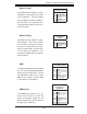
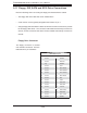
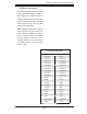
IDE Drive Connectors
Pin Defi nitions (IDE#1, IDE#2)
Pin# Defi nition Pin # Defi nition
1 Reset IDE 2 Ground
3 Host Data 7 4 Host Data 8
5 Host Data 6 6 Host Data 9
7 Host Data 5 8 Host Data 10
9 Host Data 4 10 Host Data 11
11 Host Data 3 12 Host Data 12
13 Host Data 2 14 Host Data 13
15 Host Data 1 16 Host Data 14
17 Host Data 0 18 Host Data 15
19 Ground 20 Key
21 DRQ3 22 Ground
23 I/O Write 24 Ground
25 I/O Read 26 Ground
27 IOCHRDY 28 BALE
29 DACK3 30 Ground
31 IRQ14 32 IOCS16
33 Addr1 34 Ground
35 Addr0 36 Addr2
37 Chip Select 0 38 Chip Select 1
39 Activity 40 Ground
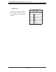
IDE Drive Connectors
There are two IDE connectors: IDE#1
(blue) and IDE#2 (white). IDE#1 is
designated as the primary IDE drive.
IDE#2 is designated as the secondary
IDE drive and is reserved for Compact
Flash card use only. See the table
below for pin defi nitions.
Note: IDE#2 is reserved for Compact
Flash card use only. Do not use it for
other devices. If IDE#2 is populated
with a Compact Flash card, IDE#1
will only support one device. For the
Compact Flash card to work properly,
you will fi rst need to connect a power
cable to JWF1.