
User Manual


6-2
SUPERSERVER 6012L-6 Manual
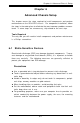
Figure 6-1. Chassis: Front and Rear Views
System Reset
6-2 Control Panel
The control panel (located on the front of the chassis) must be connected
to the JF1 connector on the motherboard to provide you with system status
indications. A ribbon cable has bundled these wires together to simplify the
connection. Connect the cable from JF1 on the motherboard to the appro-
priate header on the Control Panel PCB (printed circuit board). Make sure
the red wire plugs into pin 1 on both connectors. Pull all excess cabling out
of the airflow path.
The control panel LEDs inform you of system status. See "Chapter 3:
System Interface" an explanation of the control panel buttons and the
Onboard Indicators section in Chapter 5 for details on the motherboard
LEDs. Details on JF1 can be found in "Chapter 5: Advanced Motherboard
Installation."
Control Panel
Main Power
Slim-Line CD-ROM DriveFloppy Drive
SCSI Drives NMI
Ethernet Ports
USB Ports
Mouse Port Keyboard Port
COM1 Port
Standard Size PCI Slot
VGA Port Ext. SCSI Port
RJ45 Serial Port
USB Ports