SUPER SUPERSERVER 5017P-TLN4F 5017P-TF USER’S MANUAL 1.
The information in this User’s Manual has been carefully reviewed and is believed to be accurate. The vendor assumes no responsibility for any inaccuracies that may be contained in this document, makes no commitment to update or to keep current the information in this manual, or to notify any person or organization of the updates. Please Note: For the most up-to-date version of this manual, please see our web site at www.supermicro.com. Super Micro Computer, Inc.
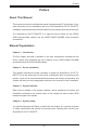
Preface Preface About This Manual This manual is written for professional system integrators and PC technicians. It provides information for the installation and use of the SuperServer 5017P-TLN4F/TF. Installation and maintainance should be performed by experienced technicians only. The SuperServer 5017P-TLN4F/TF is a high-end server based on the SC504203B rackmountable chassis and the X9SPV-LN4F/F-3610ME single processor serverboard.
SUPERSERVER 5017P-TLN4F/TF User's Manual Chapter 5: Advanced Serverboard Setup Chapter 5 provides detailed information on the X9SPV-LN4F/F-3610ME serverboard, including the locations and functions of connections, headers and jumpers. Refer to this chapter when adding or removing processors or main memory and when reconfiguring the serverboard. Chapter 6: Advanced Chassis Setup Refer to Chapter 6 for detailed information on the SC504-203B server chassis.
Preface Notes v
SUPERSERVER 5017P-TLN4F/TF User's Manual Table of Contents Chapter 1 Introduction 1-1 Overview.......................................................................................................... 1-1 1-2 Motherboard Features...................................................................................... 1-2 Processors....................................................................................................... 1-2 Memory................................................................
Table of Contents Power Fail........................................................................................................ 3-2 NIC1................................................................................................................. 3-2 NIC2................................................................................................................. 3-2 HDD.................................................................................................................. 3-3 Power....
SUPERSERVER 5017P-TLN4F/TF User's Manual 6-2 Control Panel................................................................................................... 6-2 6-3 Removing the Chassis Cover.......................................................................... 6-3 6-4 System Fans.................................................................................................... 6-4 6-5 Installing Hard Drives.......................................................................................
Chapter 1: Introduction Chapter 1 Introduction 1-1 Overview The SuperServer 5017P-TLN4F/TF is a mini server comprised of two main subsystems: the SC504-203B 1U chassis and the X9SPV-LN4F/F-3610ME single processor motherboard. Please refer to our web site for information on operating systems that have been certified for use with the system (www.supermicro.com).
SUPERSERVER 5017P-TLN4F/TF User's Manual 1-2 Motherboard Features The SuperServer 5017P-TLN4F/TF is built around the X9SPV-LN4F/F-3610ME, a single processor motherboard based on the Intel QM77 chipset and designed to provide maximum performance. Below are the main features of the X9SPV-LN4F/F3610ME. (See Figure 1-1 for a block diagram of the chipset). Processors The X9SPV-LN4F/F-3610ME supports a single Intel® Core i7 Mobile ECC processor.
Chapter 1: Introduction 1-3 Server Chassis Features The SC504-203B is an ATX form factor chassis designed to be used in a 1U rackmount configuration. The following is a general outline of the main features of the SC504-203B server chassis. System Power The SC504-203B features a single 200W power supply. Power must be removed from the system and the AC power cord removed when replacing. See Chapter 6 for details. Hard Drive Subsystem Either two 3.5" internal drive or four 2.5" internal drives (with a 2.
SUPERSERVER 5017P-TLN4F/TF User's Manual Figure 1-1. Intel QM77 Chipset: System Block Diagram Note: This is a general block diagram. Please see Chapter 5 for details. PCIe3.0_x16 PCIe x16 SLOT DDR3 (CHA) 8.0GT/s ECC-SODIMM1 1333/1067 MHz SVID DDR3 (CHB) ECC-SODIMM2 1333/1067 MHz 5.0GT/s DMI 2.0 x4 FDI X4 IMVP 7 2x SATA PORTS SATA 6Gb/s SATA[1:0] PCIE[0] PCIe1.0_x1 2.5GT/s GLAN1 82574L RJ45 4x SATA PORTS SATA 3Gb/s SATA[5:2] PCIE[1] PCIe1.0_x1 2.
Chapter 1: Introduction 1-4 Contacting Supermicro Headquarters Address: Super Micro Computer, Inc. 980 Rock Ave. San Jose, CA 95131 U.S.A. Tel: +1 (408) 503-8000 Fax: +1 (408) 503-8008 Email: marketing@supermicro.com (General Information) support@supermicro.com (Technical Support) Web Site: www.supermicro.com Europe Address: Super Micro Computer B.V. Het Sterrenbeeld 28, 5215 ML 's-Hertogenbosch, The Netherlands Tel: +31 (0) 73-6400390 Fax: +31 (0) 73-6416525 Email: sales@supermicro.
SUPERSERVER 5017P-TLN4F/TF User's Manual Notes 1-6
Chapter 2: Server Installation Chapter 2 Server Installation 2-1 Overview This chapter provides a quick setup checklist to get your SuperServer 5017PTLN4F/TF up and running. Following these steps in the order given should enable you to have the system operational within a minimum amount of time. This quick setup assumes that your system has come to you with the processors and memory preinstalled. If your system is not already fully integrated with a serverboard, processors, system memory etc.
SUPERSERVER 5017P-TLN4F/TF User's Manual • • This product is for installation only in a Restricted Access Location (dedicated equipment rooms, service closets and the like). This product is not suitable for use with visual display work place devices acccording to §2 of the the German Ordinance for Work with Visual Display Units.
Chapter 2: Server Installation Rack Mounting Considerations Ambient Operating Temperature If installed in a closed or multi-unit rack assembly, the ambient operating temperature of the rack environment may be greater than the ambient temperature of the room. Therefore, consideration should be given to installing the equipment in an environment compatible with the manufacturer’s maximum rated ambient temperature (Tmra).
SUPERSERVER 5017P-TLN4F/TF User's Manual 2-4 Installing the System into a Rack This section provides information on installing the SC504 chassis into a rack unit. There are a variety of rack units on the market, which may mean the assembly procedure will differ slightly. You should also refer to the installation instructions that came with the rack unit you are using. Installing the Chassis into a Standard Rack 1.
Chapter 2: Server Installation Telco Rack The SC504 supports Telco Rack installation. The SC504 chassis' compact design allows the it to be installed into a Telco rack without the use of rails. Figure 2-2. Installing the Chassis into a Telco Rack Installing the Chassis into a Telco Rack 1. To install the chassis into a Telco style two-post rack, use two L-shaped brackets on either side of the chassis (four total). 2. First, determine how far follow the server will extend out the front of the rack.
SUPERSERVER 5017P-TLN4F/TF User's Manual Notes 2-6
Chapter 3: System Interface Chapter 3 System Interface 3-1 Overview There are several LEDs on the control panel as well as others on the drive carriers to keep you constantly informed of the overall status of the system and the activity and health of specific components. There are also two buttons on the chassis control panel. 3-2 Control Panel Buttons There are two buttons located on the front of the chassis: a reset button and a power on/off button. Reset Use the reset button to reboot the system.
SUPERSERVER 5017P-TLN4F/TF User's Manual 3-3 Control Panel LEDs The control panel located on the front of the chassis has five LEDs. These LEDs provide you with critical information related to different parts of the system. This section explains what each LED indicates when illuminated and any corrective action you may need to take. Power Fail Indicates a power supply module has failed.
Chapter 3: System Interface HDD On the SuperServer 5017P-TLN4F/TF, this LED indicates SATA drive activity when flashing. Power Indicates power is being supplied to the system's power supply units. This LED should normally be illuminated when the system is operating. 3-4 Drive Carrier LEDs Each drive carrier has two LEDs: • • Green: When illuminated, the green LED on the SATA drive carrier indicates drive activity.
SUPERSERVER 5017P-TLN4F/TF User's Manual Notes 3-4
Chapter 4: System Safety Chapter 4 System Safety 4-1 Electrical Safety Precautions ! Basic electrical safety precautions should be followed to protect yourself from harm and the SuperServer 5017P-TLN4F/TF from damage: • • • • • • • Be aware of the locations of the power on/off switch on the chassis as well as the room's emergency power-off switch, disconnection switch or electrical outlet. If an electrical accident occurs, you can then quickly remove power from the system.
SUPERSERVER 5017P-TLN4F/TF User's Manual • Serverboard Battery: CAUTION - There is a danger of explosion if the onboard battery is installed upside down, which will reverse its polarites (see Figure 4-1). This battery must be replaced only with the same or an equivalent type recommended by the manufacturer (CR2032). Dispose of used batteries according to the manufacturer's instructions. • • 4-2 DVD-ROM Laser: CAUTION - this server may have come equipped with a DVD-ROM drive.
Chapter 4: System Safety • 4-3 After accessing the inside of the system, close the system back up and secure it to the rack unit with the retention screws after ensuring that all connections have been made. ESD Precautions ! Electrostatic discharge (ESD) is generated by two objects with different electrical charges coming into contact with each other. An electrical discharge is created to neutralize this difference, which can damage electronic components and printed circuit boards.
SUPERSERVER 5017P-TLN4F/TF User's Manual 4-4 Operating Precautions ! Care must be taken to assure that the chassis cover is in place when the 5017PTLN4F/TF is operating to assure proper cooling. Out of warranty damage to the system can occur if this practice is not strictly followed. Figure 4-1. Installing the Onboard Battery LITHIUM BATTERY LITHIUM BATTERY OR BATTERY HOLDER BATTERY HOLDER ! Please handle used batteries carefully.
Chapter 5: Advanced Motherboard Setup Chapter 5 Advanced Motherboard Setup This chapter covers the steps required to connect the data and power cables and install add-on cards. All motherboard jumpers and connections are also described. A layout and quick reference chart are included in this chapter for your reference. Remember to completely close the chassis when you have finished working with the motherboard to better cool and protect the system.
SUPERSERVER 5017P-TLN4F/TF User's Manual 5-2 Connecting Cables Now that the motherboard is installed, the next step is to connect the cables to the board. These include the data cables for the peripherals and control panel and the power cables. Connecting Data Cables The cables used to transfer data from the peripheral devices have been carefully routed to prevent them from blocking the flow of cooling air that moves through the system from front to back.
Chapter 5: Advanced Motherboard Setup Figure 5-1. Control Panel Header Pins 2 1 Power Button Ground Reset Button Ground X X Vcc OH/Fan Fail LED Vcc NIC2 LED Vcc NIC1 LED Vcc HDD LED Vcc Power LED X X NMI Ground 19 5-3 20 Rear I/O Ports The I/O ports are color coded in conformance with the PC 99 specification. See Figure 5-2 below for the colors and locations of the various I/O ports. Figure 5-2.
SUPERSERVER 5017P-TLN4F/TF User's Manual 5-4 Onboard Processor and Heatsink The X9SPV-LN4F/F-3610ME features an embedded Intel Core i7 Mobile ECC processor with an FCBGA 1023 package. 5-5 Installing Memory Caution! Exercise extreme care when installing or removing DIMM modules to prevent any possible damage. Note: Check the Supermicro website for a list of memory modules that have been validated with the X9SPV-LN4F/F-3610ME motherboard. How to Install SO DIMMs 1.
Chapter 5: Advanced Motherboard Setup The SO DIMM Socket Position the SO DIMM module's bottom key so it aligns with the receptive point on the slot. Take note of the module's side notches and the locking clips on the socket. Align Insert the SO DIMM module straight down. Press down until the module locks into place. The side clips will automatically secure the SO DIMM module, locking it into place. To Remove: Use your thumbs to gently push the side clips near both ends away from the module.
SUPERSERVER 5017P-TLN4F/TF User's Manual 5-7 Motherboard Details Figure 5-4.
Chapter 5: Advanced Motherboard Setup X9SPV-LN4F/F-3610ME Quick Reference Connector Description LED1 Standby Power LED LED2 IPMI Heartbeat LED (X9SPV-F only) LED3 Unsupported Memory LED SLOT1 PCI-E x16 Gen 2 Slot JL1 Chassis Intrusion Header JOH1 Overheat LED USB 0/1, USB 2/3 USB 3.0 Headers USB 6/7 USB 2.
SUPERSERVER 5017P-TLN4F/TF User's Manual 5-8 Connector Definitions ATX Power 24-pin Connector Pin Definitions Power Connectors The 24-pin power connector is used to provide power to the motherboard. This connector meets the SSI EPS 12V specification. See the tables on the right for pin definitions. Pin# Definition 13 +3.3V Pin # 1 +3.3V Definition 14 -12V 2 +3.
Chapter 5: Advanced Motherboard Setup NIC2 LED The LED connections for LAN2 are on pins 9 and 10 of JF1. Attach an LED cable to display network activity. See the table on the right for pin definitions. NIC2 LED Pin Definitions (JF1) Pin# Definition 9 Vcc 10 Ground NIC1 LED The LED connections for LAN1 are on pins 11 and 12 of JF1. Attach an LED cable to display network activity. See the table on the right for pin definitions.
SUPERSERVER 5017P-TLN4F/TF User's Manual LAN Ports Pin Definition Pin# Definition Ethernet Ports Four Ethernet ports are located on the I/O backplane. A dedicated IPMI LAN port is also included to provide KVM support for IPMI 2.0. These ports accept RJ45 type cables.
Chapter 5: Advanced Motherboard Setup Internal Buzzer (SP1) Pin Definition Pin# Internal Speaker The internal speaker, located at SP1, can be used to provide audible indications for various beep codes. See the table on the right for pin definitions.. Definitions Pin 1 Pos. (+) Beep In Pin 2 Neg. (-) Alarm Speaker Back Panel USB Type A USB 10 Pin Definitions Pin# Definition Universal Serial Bus (USB) Four Universal Serial Bus ports (USB 4/5, 8/9) are located on the I/O backpanel.
SUPERSERVER 5017P-TLN4F/TF User's Manual PWR LED Connector Pin Definitions Power LED/Speaker Pin Setting On the JD1 header, pins 1-3 are for a power LED and pins 4-7 are for the speaker. Close pins 4-7 with a jumper to use an external speaker. If you wish to use the onboard speaker, please close pins 6-7. See the table on the right for speaker pin definitions.
Chapter 5: Advanced Motherboard Setup DOM Power Connector A power connector for SATA DOM (Disk On Module) devices is located at JSD1. Connect an appropriate cable here to provide power support for your DOM devices. DOM PWR Pin Definitions Pin# Definition 1 +5V 2 Ground 3 Ground PWR SMB Pin Definitions Power Supply SMBus I2C Header The power System Management Bus header at JPI2C2 is used to monitor the status of the power supply, fan and system temperature.
SUPERSERVER 5017P-TLN4F/TF User's Manual 5-9 Jumper Settings Explanation of Jumpers To modify the operation of the motherboard, jumpers can be used to choose between optional settings. Jumpers create shorts between two pins to change the function of the connector. Pin 1 is identified with a square solder pad on the printed circuit board. See the motherboard layout pages for jumper locations.
Chapter 5: Advanced Motherboard Setup Watch Dog Enable/Disable Jumper JWD controls the Watch Dog function. Watch Dog is a system monitor that can reboot the system when a software application hangs. Jumping pins 1-2 will cause WD to reset the system if an application hangs. Jumping pins 2-3 will generate a non-maskable interrupt signal for the application that hangs. See the table on the right for jumper settings. Watch Dog must also be enabled in BIOS.
SUPERSERVER 5017P-TLN4F/TF User's Manual 5-10 Onboard Indicators LAN LEDs LAN1/2 LED (Connection Speed Indicator) The Ethernet ports (located beside the VGA port) have two LEDs. On each port, the yellow LED flashes to indicate activity while the other LED may be green, amber or off to indicate the speed of the connection. See the table on the right for the functions associated with the connection speed LED.
Chapter 5: Advanced Motherboard Setup 5-11 SATA and SAS Ports Serial ATA Ports Two Serial ATA (SATA) 3.0 connectors (I-SATA 0/1) are located on the motherboard. In addition, four SATA 2.0 (I-SATA 2~5) connectors are also located on the board. The SATA 3.0 ports support RAID 0, 1 while the SATA 2.0 ports support RAID 0, 1, 5 &10See the table on the right for pin definitions.
SUPERSERVER 5017P-TLN4F/TF User's Manual 5-12 Installing Software After the hardware has been installed, you should first install the operating system and then the drivers. The necessary drivers are all included on the Supermicro CDs that came packaged with your motherboard. Driver/Tool Installation Display Screen Note: Click the icons showing a hand writing on paper to view the readme files for each item.
Chapter 5: Advanced Motherboard Setup SuperDoctor III The SuperDoctor® III program is a Web base management tool that supports remote management capability. It includes Remote and Local Management tools. The local management is called SD III Client. The SuperDoctor III program included on the CD-ROM that came with your motherboard allows you to monitor the environment and operations of your system. SuperDoctor III displays crucial system information such as CPU temperature, system voltages and fan status.
SUPERSERVER 5017P-TLN4F/TF User's Manual Supero Doctor III Interface Display Screen (Remote Control) Note: The SuperDoctor III program and User's Manual can be downloaded from the Supermicro web site at http://www.supermicro.com/products/accessories/software/ SuperDoctorIII.cfm. For Linux, we recommend using SuperDoctor II.
Chapter 5: Advanced Motherboard Setup 5-21
Chapter 6: Advanced Chassis Setup Chapter 6 Advanced Chassis Setup This chapter covers the steps required to install components and perform maintenance on the SC504-203B chassis. For component installation, follow the steps in the order given to eliminate the most common problems encountered. If some steps are unnecessary, skip ahead to the step that follows. Tools Required: The only tool you will need to install components and perform maintenance is a Philips screwdriver.
SUPERSERVER 5017P-TLN4F/TF User's Manual Figure 6-1. Front and Rear Chassis Views Control Panel Power Supply Low-profile PCI Slot Rear I/O Ports (see Figure 5-2) 6-2 Control Panel The control panel (located on the front of the chassis) must be connected to the JF1 connector on the serverboard to provide you with system status indications. A ribbon cable has bundled these wires together to simplify the connection.
Chapter 6: Advanced Chassis Setup 6-3 Removing the Chassis Cover 13 12 12 12 Figure 6-2. Removing the Chassis Cover Removing the Chassis Cover 1. Power down the system and disconnect the power cord from the back of the power supply. 2. Remove the five screws that hold the chassis cover in place. There are two screws on each side of the chassis, and one screw on the back. 3. Once the screws have been removed, lift the cover upward to remove it from the chassis.
SUPERSERVER 5017P-TLN4F/TF User's Manual 6-4 System Fans (Optional) Up to three optional system fans may be installed in the SC504 chassis. Installing Optional System Fans 1. Position the dual system fan housing in the front of the chassis, facing forward as illustrated above, in front of the motherboard. 2. Align the mounting holes in the fan housing with the holes in the floor of the chassis. 3. Secure the dual fan housing to the chassis with the screws provided. 4.
Chapter 6: Advanced Chassis Setup Installing 2.5" Hard Drives 2.5" hard drives may be installed in several different configurations. Review the supported configuration options on page 6-6. 1. Power down the server, disconnect the power cord from the power supply and remove the cover. 2. Install up to four 2.5" hard drive(s) into the hard drive bracket(s) and secure them to the bracket with the screws provided. (See page 6-6 for supported configuration options.) 3.
SUPERSERVER 5017P-TLN4F/TF User's Manual Hard Drive Configuration Options 2.5" and 3.5" hard drives are supported in the following configurations: Figure 6-3. Installing Hard Drives Two 2.5" HDDs In a Double Bracket, Four HDD's Total, No Expansion Card One 3.5" Hard Drive and one Low Profile Expansion Card Two 2.5" Hard Drives and One Full-Height, HalfLength Expansion Card Two 3.
Chapter 6: Advanced Chassis Setup 6-6 Installing an Expansion Card The SC504 chassis includes a PCI slot for an optional full-height, half-length expansion card. A riser card is required in order to connect the expansion card to the motherboard. For further information on expansionon cards and risers cards, visit the Supermicro website at www.supermicro.com Expansion Card Clip Figure 6-4. Locating the Expansion Card Clip Installing the Expansion Card 1.
SUPERSERVER 5017P-TLN4F/TF User's Manual 4. Outside of the chassis, put the expansion card and the riser card together by inserting the expansion card into the riser card. 5. Simultaneously insert the PCI slot bracket of the expansion card into the open PCI slot and insert the riser card in to the riser card slot on the motherboard. Figure 6-6. Installing the Expansion Card 6. Replace the expansion card clip and screw it onto the chassis to hold the expansion card in place. 7.
Chapter 6: Advanced Chassis Setup 6-7 Power Supply The SC504 chassis has a 200 Watt power supply. This power supply is auto-switching capable. This enables it to automatically sense and operate at a 100v to 240v input voltage.In the unlikely event that the power supply module fails, the system will shut down and you will need to replace the power supply module. New units can be ordered directly from Supermicro (see contact information in the Preface).
SUPERSERVER 5017P-TLN4F/TF User's Manual 4. Remove the power supply from the chassis. 5. Align the mounting thru holes on the power supply with the mounting holes in the chassis and reattach the power supply to the chassis using the four screws which were previously set aside 6. Reconnect the wiring and the power cord to the power supply, replace the cover and power up the server.
Chapter 7: BIOS Chapter 7 BIOS 7-1 Introduction This chapter describes the AMI BIOS Setup Utility for the X9SPV-F/LN4F motherboard. The AMI ROM BIOS is stored in a Flash EEPROM and can be easily updated. This chapter describes the basic navigation of the AMI BIOS Setup Utility setup screens. Note: For instructions on BIOS recovery, please refer to the instruction guide posted at http://www.supermicro.com/support/manuals/.
SUPERSERVER 5017P-TLN4F/TF User's Manual How to Start the Setup Utility Normally, the only visible Power-On Self-Test (POST) routine is the memory test. As the memory is being tested, press the key to enter the main menu of the AMI BIOS Setup Utility. From the main menu, you can access the other setup screens. An AMI BIOS identification string is displayed at the left bottom corner of the screen, below the copyright message.
Chapter 7: BIOS System Overview: The following BIOS information will be displayed: System Time/System Date Use this option to change the system time and date. Highlight System Time or System Date using the arrow keys. Enter new values through the keyboard. Press the key or the arrow keys to move between fields. The date must be entered in Day MM/DD/YY format. The time is entered in HH:MM:SS format. (Note: The time is in the 24-hour format. For example, 5:30 P.M. appears as 17:30:00.
SUPERSERVER 5017P-TLN4F/TF User's Manual 7-3 Advanced Setup Configurations Use the arrow keys to select Boot Setup and hit to access the submenu items: BOOT Feature Quiet Boot This option allows the bootup screen options to be modified between POST messages or the OEM logo. Select Disabled to display the POST messages. Select Enabled to display the OEM logo instead of the normal POST messages. The options are Enabled and Disabled.
Chapter 7: BIOS Wait For 'F1' If Error This forces the system to wait until the 'F1' key is pressed if an error occurs. The options are Disabled and Enabled. INT19 Trap Response The Interrupt 19 (INT19) feature determines how the BIOS will react to INT19 trapping by Option ROM. If set to Immediate, BIOS will execute the trap right away. If set to Postponed, BIOS will execute the trap during legacy boot.
SUPERSERVER 5017P-TLN4F/TF User's Manual Active Processor Cores Set to Enabled to use a processor's Second Core and beyond. (Please refer to Intel's web site for more information.) The options are All, 1, 2, and 3. Limit CPUID Maximum This feature allows the user to set the maximum CPU ID value. Enable this function to boot the legacy operating systems that cannot support processors with extended CPUID functions. The options are Enabled and Disabled (for the Windows OS.).
Chapter 7: BIOS CPU PPM Configuration Power Technology This feature determines what power-saving scheme the motherboard uses. The options are Disabled, Energy Efficient and Custom. If Custom is selected, the following options become available: EIST EIST (Enhanced Intel SpeedStep Technology) allows the system to automatically adjust processor voltage and core frequency in an effort to reduce power consumption and heat dissipation. Please refer to Intel’s web site for detailed information.
SUPERSERVER 5017P-TLN4F/TF User's Manual Advanced Chipset Control WARNING: Setting the wrong values in the following sections may cause the system to malfunction. System Agent (SA) Configuration This submenu allows you to configure System Agent Parameters. Memory Configuration This section displays memory status such as memory speed and total memory. Memory Frequency Limiter Use this item to select the maximum memory frequency (in Mhz).
Chapter 7: BIOS PEG0 ASPM Set this item to control ASPM (Active State Power Management) support for PEG: Device 1 Function 0. The options are Disabled, Auto, ASPM L0s, ASPM L1, and ASPM L0sL1. Enable PEG Use this feature to enable the PEG. The options are Disabled, Enabled, and Auto. De-emphasis Control This item sets the De-emphasis control on PEG. The options are -6 dB and -3.5 dB. Initiate Graphic Adapter Use this feature to select which device will operate as the primary display.
SUPERSERVER 5017P-TLN4F/TF User's Manual EHCI Hand-Off This item is for Operating Systems that do not support Enhanced Host Controller Interface (EHCI) hand-off. When enabled, EHCI ownership change will be claimed by the EHCI driver. The settings are Enabled and Disabled. XHCI Pre-Boot Driver This feature enables support for the xHCI pre-boot driver. The options are Enabled and Disabled. XHCI Mode Use this feature to select the xHCI controller mode of operation.
Chapter 7: BIOS SLP_S4 Assertion Width Use this feature to select a minimum assertion width of the SLP_S4 signal. The options are Disabled, 1-2 Seconds, 2-3 Seconds, 3-4 Seconds, and 4-5 Seconds. IDE/SATA Configuration When this submenu is selected, the AMI BIOS automatically detects the presence of the SATA Devices and displays the following items: SATA Controllers This item enables or disables the on board SATA controller.
SUPERSERVER 5017P-TLN4F/TF User's Manual RAID Mode The following items are displayed when RAID Mode is selected: Serial ATA Port 0~5 Hot Plug Set this item to Enabled to enable hot-plugging for the particular port. The options are Enabled and Disabled. Serial ATA Port 0~5 Spin Up Device Set this item to Enabled to enable device spin-up support. The options are Enabled and Disabled.
Chapter 7: BIOS Maximum Payload This feature selects the setting for the PCIE maximum payload size. The options are Auto, 128 Bytes, and 256 Bytes, 512 Bytes, 1024 Bytes, 2048 Bytes, and 4096 Bytes. Maximum Read Request This feature selects the setting for the PCIE maximum Read Request size. The options are Auto, 128 Bytes, 256 Bytes, 512 Bytes, 1024 Bytes, 2048 Bytes, and 4096 Bytes. Above 4G Decoding Set this item to Enabled to activate 64-bit capable devices to be decoded above the 4G address space.
SUPERSERVER 5017P-TLN4F/TF User's Manual Maximum Read Request This feature selects the setting for the PCI Express maximum Read Request size. The options are Auto, 128 Bytes, 256 Bytes, 512 Bytes, 1024 Bytes, 2048 Bytes, and 4096 Bytes. ASPM Support Set this item to the desired ASPM (Active State Power Management) level. The options are Disabled, Auto and Force L0s. Extended Synch Select Enabled for Extended Synchronization support, which will extend the same synchronization patterns for the PCI-E device.
Chapter 7: BIOS Configuration Request, permitting access to Extended Functions in an ARI device immediately below the port. The options are Disabled and Enabled. AtomicOp Requester Enable (Available when supported by the hardware) When set to Enabled, this feature initiates AtomicOp requests only if Bus Master Enable bit is in the Command Register set. The options are Disabled and Enabled.
SUPERSERVER 5017P-TLN4F/TF User's Manual Compliance SOS (Available when supported by the hardware) When set to Enabled, this feature will force LTSSM to send SKP ordered sets between sequences when sending compliance pattern or modified compliance pattern. The options are Disabled and Enabled.
Chapter 7: BIOS Ipv6 PXE Support This feature enables Ipv6 boot support. If disabled, an Ipv6 PXE boot option will not be created. The options are Enabled and Disabled. Super IO Device Configuration Serial Port 1 Configuration / Serial Port 2 Configuration Serial Port 1 / Serial Port 2 Select Enabled to enable the onboard serial port. The options are Enabled and Disabled.
SUPERSERVER 5017P-TLN4F/TF User's Manual Remote Access Configuration COM1, COM2, SOL Console Redirection Use this feature to enable console redirection for COM1, and COM2 ports. The options are Enabled and Disabled. The default for COM1 and COM2 is Disabled. The default for SOL is Enabled. Console Redirection Settings This feature allows the user to specify how the host computer will exchange data with the client computer, which is the remote computer used by the user.
Chapter 7: BIOS Flow Control This feature allows the user to set the flow control for Console Redirection to prevent data loss caused by buffer overflow. Send a "Stop" signal to stop sending data when the receiving buffer is full. Send a "Start" signal to start sending data when the receiving buffer is empty. The options are None and Hardware RTS/CTS. VT-UTF8 Combo Key Support Select Enabled to enable VT-UTF8 Combination Key support for ANSI/VT100 terminals. The options are Enabled and Disabled.
SUPERSERVER 5017P-TLN4F/TF User's Manual Console Redirection Settings (for EMS) This feature allows the user to specify how the host computer will exchange data with the client computer, which is the remote computer used by the user. Out-of-Band-Mgmt Port Use this feature to select the port for out-of-band management. The options are COM1, COM2, and SOL. Terminal Type This feature allows the user to select the target terminal emulation type for Console Redirection.
Chapter 7: BIOS ACPI Sleep State This setting allows you to configure the ACPI (Advanced Configuration and Power Interface) sleep state for your system when it is in the Suspend mode. The options are Suspend Disabled, S1 only (CPU Stop Clock), S3 only (Suspend to RAM), and Both S1 and S3 available for OS to choose from. S3 (Suspend to RAM) is the deepest sleep state in these options. PS2 KB/MS Wake up Use this feature to select the PS2 Keyboard/Mouse wake up setting.
SUPERSERVER 5017P-TLN4F/TF User's Manual Add an Attempt The settings on this section are setup parameters to connect to a remote iSCSI device. iSCSI Attempt Name - assigns a unique name to this attempt. iSCSI Mode - select Enabled or Disabled Connection Retry Count - if the initial connection fails or times out, this is how many times an attempt will be made to connect. Connection Establishing Timeout - This is the time in milliseconds the system will wait for a connection until it times out.
Chapter 7: BIOS Intel(R) 82579LM / Intel(R) 82574L Gigabit Network Connection NIC Configuration Link Speed Use this feature to select the link speed to be used. The options are AutoNeg, 10 Mbps Half, 10 Mbps Full, 100 Mbps Half and 100 Mbps Full. Wake On LAN Use this feature to activate the Wake On LAN (WOL) feature. The options are Enabled, and Disabled. Blink LEDs (Range 0-15 seconds) Please specifies the blink rate of the NIC LED. Select from 1-15 second intervals.
SUPERSERVER 5017P-TLN4F/TF User's Manual Change SmBIOS Event Log Settings Smbios Event Log Change this item to enable or disable all features of the Smbios Event Logging during boot. The options are Enabled and Disabled. Erase Event Log This option erases all logged events. The options are No, Yes, Next reset and Yes, Every reset. When Log is Full This option automatically clears the Event Log memory of all messages when it is full. The options are Do Nothing and Erase Immediately.
Chapter 7: BIOS 7-5 IPMI Settings Intelligent Platform Management Interface (IPMI) is a set of common interfaces that IT administrators can use to monitor system health and to manage the system as a whole. For more information on the IPMI specifications, please visit Intel's website at www.intel.com. System Event Log This feature is used to change the System Event Log (SEL) configuration. SEL Components - Change this item to enable or disable all features of System Event Logging.
SUPERSERVER 5017P-TLN4F/TF User's Manual Log EFI Status Codes This option enables or disables the logging of Extensible Firmware Interface (EFI) status codes. The options are Disabled, and Enabled. BMC Network Configuration Set this feature to configure the IPMI LAN adapter with a network address. Update IPMI LAN Configuration This feature allows the user to decide if the BIOS should configure the IPMI setting at next system boot. The options are No and Yes.
Chapter 7: BIOS 7-6 Boot Use this feature to configure Boot Settings: Setup Prompt Timeout Use this feature to enter the number of seconds to wait for setup activation key. The default setting is 1 second. Boot Options Priorities This feature allows the user to specify which devices are boot devices and the order of priority from which the system boots during startup. Boot Option #1, Boot option #2, Boot Option #3, etc The settings are [any detected boot device] and Disabled.
SUPERSERVER 5017P-TLN4F/TF User's Manual 7-7 Security Settings • If the Administrator password is defined ONLY - this controls access to the BIOS setup ONLY. • If the User's password is defined ONLY - this password will need to be entered during each system startup or boot, and will also have Administrator rights in the setup. • Passwords must be at least 3 and up to 20 characters long. Administrator Password Press Enter to create a new, or change an existing Administrator password.
Chapter 7: BIOS 7-8 Exit Select the Exit tab from the BIOS Setup Utility screen to enter the Exit BIOS Setup screen. Discard Changes and Exit Select this option to quit the BIOS Setup without making any permanent changes to the system configuration, and reboot the computer. Select Discard Changes and Exit from the Exit menu and press .
SUPERSERVER 5017P-TLN4F/TF User's Manual Restore Defaults To set this feature, select Restore Defaults from the Exit menu and press . These are factory settings designed for maximum system stability, but not for maximum performance. Save As User Defaults To set this feature, select Save as User Defaults from the Exit menu and press .
Appendix A: POST Error Beep Codes Appendix A POST Error Beep Codes This section lists POST (Power On Self Test) error beep codes for the AMI BIOS. POST error beep codes are divided into two categories: recoverable and terminal. This section lists Beep Codes for recoverable POST errors. Recoverable POST Error Beep Codes When a recoverable type of error occurs during POST, BIOS will display a POST code that describes the problem.
SUPERSERVER 5017P-TLN4F/TF User's Manual Notes A-2
Appendix B: System Specifications Appendix B System Specifications Processors Single or dual Intel® Xeon Core i7 Mobile ECC processor Note: Please refer to our web site for a complete listing of supported processors. Chipset Intel QM77 chipset BIOS 16 MB AMI® SPI Flash ROM Memory Capacity Two SO-DIMM slots that can support up to 16 GB of unbuffered DDR31333/1066/800 memory Note: see Section 5-6 for details. Drive Bays Two 3.5" internal drives or four 2.
SUPERSERVER 5017P-TLN4F/TF User's Manual System Input Requirements AC Input Voltage: 100 - 240V AC auto-range Rated Input Current: 2.6A max Rated Input Frequency: 50 to 60 Hz Power Supply Rated Output Power: 200W (Part# PWS-203-1H) Rated Output Voltages: +5V (8A), +12V (16A), +3.
Appendix B: System Specifications Notes B-1
SUPERSERVER 5017P-TLN4F/TF User's Manual (continued from front) The products sold by Supermicro are not intended for and will not be used in life support systems, medical equipment, nuclear facilities or systems, aircraft, aircraft devices, aircraft/emergency communication devices or other critical systems whose failure to perform be reasonably expected to result in significant injury or loss of life or catastrophic property damage.