
Instruction Manual


Chapter 2: Installation
2-13
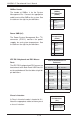
Fan Header
Pin Defi nitions
Pin# Defi nition
1 Ground
2 +12V
3 Tachometer
4 PWR Modulation
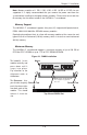
Fan Headers
This motherboard has nine fan headers
(Fan1 to Fan9). These 4-pin fans headers
are backward compatible with 3-pin fans.
However, fan speed control is available
for 4-pin fans only. The fan speeds are
controlled by the BIOS. See the table on the
right for pin defi nitions
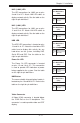
Serial Ports
The COM1 serial port is located beside the
VGA port. Refer to the motherboard layout
for the location of the COM2 header. See the
table on the right for pin defi nitions.
Serial Port Pin Defi nitions
(COM1/COM2)
Pin # Defi nition Pin # Defi nition
1 DCD 6 DSR
2 RXD 7 RTS
3 TXD 8 CTS
4 DTR 9 RI
5 Ground 10 NC
Note: NC indicates no connection.
Wake-On-LAN
The Wake-On-LAN header is designated
JWOL. See the table on the right for pin
defi nitions. You must have a LAN card with
a Wake-On-LAN connector and cable to use
the Wake-On-LAN feature.
Wake-On-LAN
Pin Defi nitions
(JWOL)
Pin# Defi nition
1 +5V Standby
2 Ground
3 Wake-up
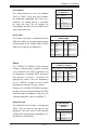
SGPIO
The T-SGPIO1/ T-SGPIO2 (Serial General
Purpose Input/Output) headers provide
a bus between the SATA controller and
the backpane to provide SATA enclosure
management functions. Connect the
appropriate cable from the backplane
to the T-SGPIO1 header to utilize SATA
management functions on your system.
Likewise, the 3-SGPIO1/3-SGPIO2 headers
provide the same function between the SAS
controller and the backpane, and have the
same pin defi nitions (only on H8QG6+-F).
SGPIO Header Pin Defi nitions
(T-SGPIO1/T-SGPIO2)
Pin# Defi nition Pin # Defi nition
1 NC 2 Data
3 Ground 4 Data
5 Load 6 Ground
7 CLK 8 NC
Note: NC indicates no connection.