
User's Manual


2-28
X8ST3-F/X8STE User's Manual
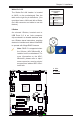
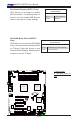
BMC JTAG
1
SAS1
SAS2
SAS7
SAS3
SAS4
SAS5
SAS6
JWOL
Battery
JD1
SPKR1
JAR
JI2C1
JI2C2
JPS2
JL1
1
JOH
1
JF1
LES1
LE1
COM1
FA N 4
FA N 3
FA N 5
FA N 2
FA N 1
JPW1
SMBUS_PS1
JPW2
JPG1
JPUSB3
JBMC1
JPS1
JPUSB2
JPL1
JPL2
JLED
JWD
JPUSB1
IPMI_LAN
COM2
Floppy
I-Button
T-SGPIO1
3-SGPIO2
3-SGPIO1
USB 6/7
USB 4/5
USB3
USB2
Slot6 PCI-E 2.0 X8 on X16
Slot3 PCI-E 2.0 X8
I-SATA4
I-SATA5
Slot4 PCI-E 2.0 X4 on X8
Slot2 PCI 33MHz
Slot5 PCI-E 2.0 X8
I-SATA2
I-SATA3
DIMM1B
DIMM1A
DIMM3B
DIMM2B
DIMM2A
DIMM3A
I-SATA0
I-SATA1
X8ST3-F/X8STE
USB 0/1
LAN2
LAN1
VGA
KB/MOUSE
BIOS
JBT1
Slot1 PCI 33MHz
SAS0
T-SGPIO2
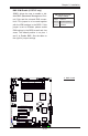
LAN CTRL
for IPMIl LAN
LAN
CTRL1
LAN
CTRL2
SI/O
BMC CTRL
BMC
Firmware
SAS CTRL
Intel ICH10R
South Bridge
Intel X58-Express
North Bridge
Intel Processor
LES2
LSI 1068E
WPCM 450
CPU FAN
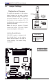
2-7 Jumper Settings
Explanation of Jumpers
To modify the operation of the mother-
board, jumpers can be used to choose
between optional settings. Jumpers cre-
ate shorts between two pins to change
the function of the connector. Pin 1 is
identied with a square solder pad on the
printed circuit board.
Note: On two pin jumpers, "Closed"
means the jumper is on and "Open"
means the jumper is off the pins.
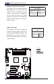
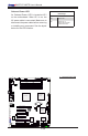
A
A. LAN Port 1 Enable
B. LAN Port 2 Enable
LAN Port Enable/Disable
JPL1/JPL2 enable or disable LAN
Port 1/LAN Port 2 on the mother-
board. See the table on the right for
jumper settings. The default setting
is enabled.
GLAN Enable
Jumper Settings
Pin# Denition
1-2 Enabled (default)
2-3 Disabled
B