
User's Manual


Chapter 2: Installation
2-19
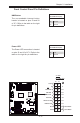
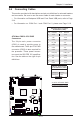
Power Button
OH/Fan Fail LED
1
NIC1 LED
Reset Button
2
HDD LED
Power LED
Reset
PWR
Vcc
Vcc
Vcc
Vcc
Ground
Ground
1920
Vcc
X
Ground
NMI
X
Vcc
PWR Fail LED
NIC2 LED
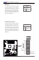
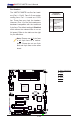
Overheat (OH)/Fan Fail LED
Connect an LED cable to the OH/
Fan Fail connection on pins 7 and 8
of JF1 to provide advanced warnings
for chassis overheat or fan failure.
Refer to the table on the right for pin
denitions.
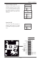
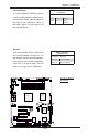
Power Fail LED
The Power Fail LED connection is
located on pins 5 and 6 of JF1. Refer
to the table on the right for pin deni-
tions.
OH/Fan Fail LED
PinDenitions(JF1)
Pin# Denition
7 Vcc
8 Ground
OH/Fan Fail Indicator
Status
State Denition
Off Normal
On Overheat
Flash-
ing
Fan Fail
PWR Fail LED
PinDenitions(JF1)
Pin# Denition
5 Vcc
6 Ground
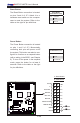
A
B
A. OH/Fan Fail LED
B. PWR Supply Fail
X8ST3-F/X8STE