X10SLQ X10SLQ-L USER’S MANUAL Revision 1.
The information in this User’s Manual has been carefully reviewed and is believed to be accurate. The vendor assumes no responsibility for any inaccuracies that may be contained in this document, makes no commitment to update or to keep current the information in this manual, or to notify any person or organization of the updates. Please Note: For the most up-to-date version of this manual, please see our web site at www.supermicro.com. Super Micro Computer, Inc.
Preface Preface This manual is written for system integrators, PC technicians and knowledgeable PC users. It provides information for the installation and use of the X10SLQ/X10SLQ-L motherboard. About This Motherboard The X10SLQ/X10SLQ-L supports the 4th generation Intel® Core™ i7/i5/i3, Pentium, and Celeron processor in an LGA 1150 (H3) socket.
X10SLQ/X10SLQ-L User’s Manual Conventions Used in the Manual: Special attention should be given to the following symbols for proper installation and to prevent damage done to the components or injury to yourself: Warning: Critical information to prevent damage to the components or injury to yourself. Important: Important information is given to ensure proper system installation or to relay safety precautions. Note: Additional Information is provided for correct system setup.
Contacting Supermicro Contacting Supermicro Headquarters Address: Super Micro Computer, Inc. 980 Rock Ave. San Jose, CA 95131 U.S.A. Tel: +1 (408) 503-8000 Fax: +1 (408) 503-8008 Email: marketing@supermicro.com (General Information) support@supermicro.com (Technical Support) Web Site: www.supermicro.com Europe Address: Super Micro Computer B.V. Het Sterrenbeeld 28, 5215 ML 's-Hertogenbosch, The Netherlands Tel: +31 (0) 73-6400390 Fax: +31 (0) 73-6416525 Email: sales@supermicro.
X10SLQ/X10SLQ-L User’s Manual Table of Contents Preface Chapter 1 Introduction 1-1 Overview.......................................................................................................... 1-1 1-2 Chipset Overview ...........................................................................................1-11 1-3 Special Features............................................................................................ 1-12 1-4 PC Health Monitoring...........................................
Table of Contents VESA DisplayPort...................................................................................... 2-20 HDMI Port.................................................................................................. 2-20 VGA/DVI-D Connections........................................................................... 2-21 Front Control Panel........................................................................................ 2-22 Front Control Panel Pin Definitions.......................
X10SLQ/X10SLQ-L User’s Manual Chapter 3 Troubleshooting 3-1 Troubleshooting Procedures............................................................................ 3-1 3-2 Technical Support Procedures......................................................................... 3-3 3-3 Frequently Asked Questions............................................................................ 3-3 3-4 Battery Removal and Installation.....................................................................
Chapter 1: Introduction Chapter 1 Introduction 1-1 Overview Checklist Congratulations on purchasing your computer motherboard from an acknowledged leader in the industry. Supermicro boards are designed with the utmost attention to detail to provide you with the highest standards in quality and performance. Please check that the following items have all been included with your motherboard. If anything listed here is damaged or missing, contact your retailer.
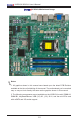
X10SLQ/X10SLQ-L User’s Manual X10SLQ Motherboard Image Notes: 1. All graphics shown in this manual were based upon the latest PCB Revision available at the time of publishing of the manual. The motherboard you've received may or may not look exactly the same as the graphics shown in this manual. 2. The following components are not available on the X10SLQ-L model: DIMM A1/ DIMM B1, Keyboard/Mouse, USB (2.0) 0/1, (3.0) 10/11, and the mini-PCIe card with mSATA and 3G socket support.
Chapter 1: Introduction X10SLQ/X10SLQ-L Motherboard Layout LAN2 LAN1 USB4/5 USB2/3(3.0) Not On “-L Model” HDMI/DP KB/MOUSE Not On “-L Model” AUDIO FP VGA/DVI HD AUDIO JPL2 JHD_AC1 JPAC1 JPL1 JPW2 FAN4 Rev. 1.
X10SLQ/X10SLQ-L User’s Manual X10SLQ/X10SLQ-L Quick Reference LAN 2 USB 4/5 LAN 1 USB 2/3 HDMI/DP VGA DVI-D KB/MOUSE USB 0/1 Not On “-L Model” AUDIO FP HD AUDIO USB 2/3 JPAC1 Rev. 1.
Chapter 1: Introduction X10SLQ/X10SLQ-L Headers/Connectors Connector Description Audio FP Front Panel Audio Header HD AUDIO High-Definition Audio Connectors (on the I/O back panel) Battery Onboard Battery COM1-COM4 COM1/COM2/COM3/COM4 Port Headers Fan1-Fan4 System/CPU Fan Headers (Fan1: CPU Fan) HDMI/DP Backpanel HDMI/DisplayPort JD1 Speaker/buzzer (Pins 3-4: Buzzer, Pins 1-4: External Speaker) JF1 Front Panel Control Header JL1 Chassis Intrusion Header JLED1 Power LED Indicator Header
X10SLQ/X10SLQ-L User’s Manual X10SLQ/X10SLQ-L LED Indicators LED Description Color/State Status LED1 Onboard Standby PWR LED Green: Solid on Power On LED2 WLAN_LED LED3 Standby Power LED Green: Solid on Power On 1-6
Chapter 1: Introduction Motherboard Features CPU 4th Generation Intel® Core™ i7/i5/i3, Pentium, and Celeron processor in an LGA1150 socket. Memory Four (4) SDRAM slots support up to 32 GB of DDR3 Unbuffered, Non-ECC 1600/1333 MHz memory for the X10SLQ. Two (2) SDRAM slots support up to 16 GB of DDR3 Unbuffered, Non-ECC 1600/1333 MHz memory for the X10SLQ-L. Dual-channel memory DIMM sizes UDIMM 1 GB, 2 GB, 4GB, and 8GB Chipset Intel® Q87 Express Expansion Slots One (1) PCI Express 3.
X10SLQ/X10SLQ-L User’s Manual One (1) mini-PCI-Express socket shared with mSATA (Not available on the -L model). Video and Graphics One (1) High Definition Multimedia Interface (HDMI), one (1) DisplayPort, one (1) DVI-D, and one (1) VGA from Intel Processor Graphics, support three independent Displays. Audio One (1) High Definition Multimedia Interdace (HDMI), one (1) DisplayPort, and one (1) High Definition Audio 7.1 channel connector on the back panel.
Chapter 1: Introduction CD Utilities Download from www.supermicro.com Drivers/Software for Intel® Q87 Express Chipset Utilities Other ROHS (Full Compliance, Lead Free) Operating Temperature: 0-60C Dimensions Micro-ATX form factor (9.60" x 9.60") (243.84 mm x 243.
X10SLQ/X10SLQ-L User’s Manual X10SLQ/X10SLQ-L Block Diagram PCIe x16 SLOT #7 DisplayPort PCIe3.0_x16 8.0GT/s Digital port B HDMI Digital port C DVI-D Digital port D VRD12.5 INTEL LGA1150 Haswell-DT (Socket-H3) PCIe x4 SLOT #4 Mini PCI-E SLOT Shared with mSATA PCIe2.0_x1 5GT/s PCIe2.0_x4 5GT/s PCIe2.0_x1 5GT/s SATA-III 600MB/s 8 USB 2.0 PORTS SATA-III 600MB/s USB2.0 480Mbps 4 USB 3.0 PORTS USB3.0 480Mbps 5 SATA-III PORTS Realtek ALC888S-VD2 AZALIA VRM 12.
Chapter 1: Introduction 1-2 Chipset Overview The X10SLQ/X10SLQ-L supports a single 4th generation Intel® Core i7/i5/i3, Pentium, and Celeron processor in the LGA 1150 Socket. Built upon the functionality and the capability of the Q87 Express chipset, the motherboard provides substantial enhancement to system performance and storage capability for high performance platforms in a sleek package.
X10SLQ/X10SLQ-L User’s Manual 1-3 Special Features Recovery from AC Power Loss Basic I/O System (BIOS) provides a setting for you to determine how the system will respond when AC power is lost and then restored to the system. You can choose for the system to remain powered off, (in which case you must press the power switch to turn it back on), or for it to automatically return to a power-on state. See the Advanced BIOS Setup section to change this setting. The default setting is Last State.
Chapter 1: Introduction is used to notify the user of certain system events. For example, you can also configure SuperDoctor to provide you with warnings when the system temperature, CPU temperatures, voltages and fan speeds go beyond predefined thresholds. 1-5 ACPI Features ACPI stands for Advanced Configuration and Power Interface.
X10SLQ/X10SLQ-L User’s Manual 2. To provide adequate power to SATA devices, please connect the SATA DOM PWR connector (JSD1) to the power supply. It is strongly recommended that you use a high quality power supply that meets ATX power supply Specification 2.02 or above. It must also be SSI compliant. (For more information, please refer to the web site at http://www.ssiforum.org/).
Chapter 2: Installation Chapter 2 Installation 2-1 Standardized Warning Statements The following statements are industry-standard warnings, provided to warn the user of situations which have the potential for bodily injury. Should you have questions or experience difficulty, contact Supermicro's Technical Support department for assistance. Only certified technicians should attempt to install or configure components.
X10SLQ/X10SLQ-L User’s Manual Attention Danger d'explosion si la pile n'est pas remplacée correctement. Ne la remplacer que par une pile de type semblable ou équivalent, recommandée par le fabricant. Jeter les piles usagées conformément aux instructions du fabricant. ¡Advertencia! Existe peligro de explosión si la batería se reemplaza de manera incorrecta. Reemplazar la batería exclusivamente con el mismo tipo o el equivalente recomendado por el fabricante.
Chapter 2: Installation Product Disposal Warning! Ultimate disposal of this product should be handled according to all national laws and regulations. 製品の廃棄 この製品を廃棄処分する場合、国の関係する全ての法律・条例に従い処理する必要が あります。 警告 本产品的废弃处理应根据所有国家的法律和规章进行。 警告 本產品的廢棄處理應根據所有國家的法律和規章進行。 Warnung Die Entsorgung dieses Produkts sollte gemäß allen Bestimmungen und Gesetzen des Landes erfolgen. ¡Advertencia! Al deshacerse por completo de este producto debe seguir todas las leyes y reglamentos nacionales.
X10SLQ/X10SLQ-L User’s Manual عند التخلص النهائي من هذا المنتج ينبغي التعامل معه وفقا لجميع القىانين واللىائح الىطنية 경고! 이 제품은 해당 국가의 관련 법규 및 규정에 따라 폐기되어야 합니다. Waarschuwing De uiteindelijke verwijdering van dit product dient te geschieden in overeenstemming met alle nationale wetten en reglementen. 2-2 Static-Sensitive Devices Electrostatic-Discharge (ESD) can damage electronic components. To avoid damaging your system board, it is important to handle it very carefully.
Chapter 2: Installation 2-3 Processor and Heatsink Installation Warning: When handling the processor package, avoid placing direct pressure on the label area of the fan. Important: • • • • • Always connect the power cord last, and always remove it before adding, removing or changing any hardware components. Make sure that you install the processor into the CPU socket before you install the CPU heatsink.
X10SLQ/X10SLQ-L User’s Manual 2. Gently lift the load lever to open the load plate. Remove the plastic cap. 3. Use your thumb and your index finger to hold the CPU at the North center edge and the South center edge of the CPU. North Center Edge South Center Edge 4. Align the CPU key that is the semi-circle cutouts against the socket keys. Once it is aligned, carefully lower the CPU straight down into the socket. Do not drop the CPU on the socket. Do not move the CPU horizontally or vertically.
Chapter 2: Installation 5. Do not rub the CPU against the surface or against any pins of the socket to avoid damaging the CPU or the socket.) 6. With the CPU inside the socket, inspect the four corners of the CPU to make sure that the CPU is properly installed. 7. Use your thumb to gently push the load lever down to the lever lock. CPU properly installed Load lever locked into place Warning: You can only install the CPU inside the socket only in one direction.
X10SLQ/X10SLQ-L User’s Manual Installing an Active CPU Heatsink with Fan 1. Locate the CPU Fan power connector on the motherboard. (Refer to the layout on the right for the CPU Fan location.) 2. Position the heatsink so that the heatsink fan wires are closest to the CPU fan power connector and are not interfered with other components. Thermal Grease 3. Inspect the CPU Fan wires to make sure that the wires are routed through the bottom of the heatsink. 4.
Chapter 2: Installation 7. Align the four heatsink fasteners with the mounting holes on the motherboard. Gently push the pairs of diagonal fasteners (#1 & #2, and #3 & #4) into the mounting holes until you hear a click. Also, make sure to orient each fastener so that the narrow end of the groove is pointing outward. 8. Repeat Step 7 to insert all four heatsink fasteners into the mounting holes. 9.
X10SLQ/X10SLQ-L User’s Manual Removing the Heatsink Warning: We do not recommend that the CPU or the heatsink be removed. However, if you do need to remove the heatsink, please follow the instructions below to remove the heatsink and to prevent damage done to the CPU or other components. Active Heatsink Removal 1. Unplug the power cord from the power supply. Unplug the PWR cord 2. Disconnect the heatsink fan wires from the CPU fan header. 3.
Chapter 2: Installation 2-4 Installing DDR3 Memory Note: Check the Supermicro website for recommended memory modules. CAUTION Exercise extreme care when installing or removing DIMM modules to prevent any possible damage. LAN1 LAN2 VGA/DVI USB4/5 JPL2 JHD_AC1 JPAC1 USB2/3(3.0) Not On “-L Model” X10SLQ (-L) Rev. 1.
X10SLQ/X10SLQ-L User’s Manual Removing Memory Modules Reverse the steps above to remove the DIMM modules from the motherboard. Memory Support Towards the CPU Not available on the -L model Channel A, Slot1 Channel A, Slot2 (Blue Slot) Not available on the -L model Channel B, Slot1 Channel B, Slot2 (Blue Slot) Towards the edge of the motherboard The X10SLQ supports up to 32GB of Unbuffered (UDIMM) DDR3 Non-ECC 1600/1333 MHz in 4 memory slots.
Chapter 2: Installation • Due to memory allocation to system devices, the amount of memory that remains available for operational use will be reduced when 4 GB of RAM is used. The reduction in memory availability is disproportional. See the following table for details. • For Microsoft Windows users: Microsoft implemented a design change in the Windows XP with Service Pack 2 (SP2) and Windows Vista.
X10SLQ/X10SLQ-L User’s Manual 2-5 Motherboard Installation All motherboards have standard mounting holes to fit different types of chassis. Make sure that the locations of all the mounting holes for both motherboard and chassis match. Although a chassis may have both plastic and metal mounting fasteners, metal ones are highly recommended because they ground the motherboard to the chassis. Make sure that the metal standoffs click in or are screwed in tightly.
Chapter 2: Installation Installing the Motherboard 1. Install the I/O shield into the back of the chassis. 2. Locate the mounting holes on the motherboard. (See the previous page.) 3. Locate the matching mounting holes on the chassis. Align the mounting holes on the motherboard against the mounting holes on the chassis. 4. Install standoffs in the chassis as needed. 5. Install the motherboard into the chassis carefully to avoid damaging other motherboard components. 6.
X10SLQ/X10SLQ-L User’s Manual 2-6 Connectors/IO Ports The I/O ports are color coded in conformance with the industry standards. See the figure below for the colors and locations of the various I/O ports. Backplane I/O Panel LAN2 LAN1 USB4/5 USB2/3(3.0) Not On “-L Model” HDMI/DP KB/MOUSE Not On “-L Model” AUDIO FP VGA/DVI HD AUDIO JPL2 JHD_AC1 JPAC1 Rev. 1.00 JPL1 USB0/1 JPW2 FAN4 SLOT7 PCI-E 3.0 X16 SLOT5 PCI-E 2.
Chapter 2: Installation ATX PS/2 Keyboard/Mouse Ports (Not available on the -L model) The ATX PS/2 keyboard and PS/2 mouse are located above Back Panel USB Ports 0/1 on the motherboard. See the table on the right for pin definitions.
X10SLQ/X10SLQ-L User’s Manual Universal Serial Bus (USB) Four Universal Serial Bus 2.0 ports (0/1, 4/5) and two USB 3.0 ports (2/3) are located on the I/O back panel. In addition, two USB 2.0 headers (four USB 2.0 connections: 6/7, 8/9), and one USB 3.0 header (one USB 3.0 connections: 10/11) are also located on the motherboard to provide front chassis access using USB cables (not included). See the tables below for pin definitions. Front Panel USB (2.
Chapter 2: Installation Ethernet Ports LAN Ports Pin Definition Two Gigabit Ethernet ports (LAN1/ LAN2) are located next to the Pin# Definition HD Audio Connector on the I/O Backpanel to provide network connections. These ports accept RJ45 type cables. Note: Please refer to the LED Indicator Section for LAN LED information.
X10SLQ/X10SLQ-L User’s Manual Front Accessible Audio Header 10-in Audio Pin Definitions A 10-pin Audio header is also located on the motherboard. This header allows you to use the onboard sound for audio playback. Connect an audio cable to the audio header to use this feature. See the table on the right for pin definitions for the header. VESA DisplayPort DisplayPort, developed by the VESA consortium, delivers digital display and fast refresh rate.
Chapter 2: Installation VGA/DVI-D Connections A VGA port and a DVI-D connector are located next to USB Ports 0/1 on the I/O backpanel. Use these connections for VGA and DVI-D displays. LAN2 LAN1 USB4/5 USB2/3(3.
X10SLQ/X10SLQ-L User’s Manual Front Control Panel JF1 contains header pins for various buttons and indicators that are normally located on a control panel at the front of the chassis. These connectors are designed specifically for use with Supermicro chassis. See the figure below for the descriptions of the front control panel buttons and LED indicators. Refer to the following section for descriptions and pin definitions. LAN2 LAN1 USB4/5 USB2/3(3.
Chapter 2: Installation Front Control Panel Pin Definitions Power LED Power LED Pin Definitions (JF1) The Power LED connection is located on pins 15 and 16 of JF1. Refer to the table on the right for pin definitions. HDD LED LAN1 HDMI/DP Not On “-L Model” AUDIO FP HD AUDIO USB4/5 JPL2 JHD_AC1 JPAC1 USB2/3(3.
X10SLQ/X10SLQ-L User’s Manual NIC1/NIC2 (LAN1/LAN2) LAN1/LAN2 LED Pin Definitions (JF1) The NIC (Network Interface Controller) LED connection for LAN port 1 is located Pin# on pins 11 and 12 of JF1, and the LED connection for LAN Port 2 is on Pins 9 and 10. NIC1 LED and NIC2 LED are 2-pin NIC LED headers. Attach NIC LED cables to NIC1 and NIC2 LED indicators to display network activities. Refer to the table on the right for pin definitions.
Chapter 2: Installation Reset Button The Reset Button connection is located on pins 3 and 4 of JF1. Attach it to a hardware reset switch on the computer case to reset the system. Refer to the table on the right for pin definitions. Reset Button Pin Definitions (JF1) Pin# Definition 3 Reset 4 Ground Power Button The Power Button connection is located on pins 1 and 2 of JF1. Momentarily contacting both pins will power on/off the system.
X10SLQ/X10SLQ-L User’s Manual 2-7 Connecting Cables This section provides brief descriptions and pin-out definitions for onboard headers and connectors. Be sure to use the correct cable for each header or connector. For information on Backpanel USB and Front Panel USB ports, refer to Section 2-6. ATX Power 24-pin Connector Pin Definitions (JPW1) ATX Main PWR & CPU PWR Connectors (JPW1 & JPW2) Pin# Definition 13 +3.3V 1 +3.
Chapter 2: Installation Fan Headers (Fan 1 - Fan 4) Fan Header Pin Definitions The X10SLQ/X10SLQ-L has four fan headers (Fan 1-Fan 4). These fans are 4-pin fan headers. Although pins 1-3 of the fan headers are backward compatible with the traditional 3-pin fans, we recommend the use 4-pin fans to take advantage of the fan speed control. This allows the fan speeds to be automatically adjusted based on the motherboard temperature. Refer to the table on the right for pin definitions.
X10SLQ/X10SLQ-L User’s Manual Internal Buzzer (SP1) Internal Buzzer Pin Definition The Internal Buzzer (SP1) can be used to provide audible indications for Pin# various beep codes. See the table on the right for pin definitions. Pin 1 Pos. (+) Beep In Pin 2 Neg. (-) Alarm Speaker Definitions Speaker (JD1) Speaker Connector Pin Definitions On the JD1 header, pins 3-4 are used for internal speaker. Close pins 3-4 with a cap to use the onboard speaker.
Chapter 2: Installation Onboard Power LED (JLED1) Onboard PWR LED Pin Definitions An onboard Power LED header is located at JLED1. This Power LED header is connected to Front Control Panel located at JF1 to indicate the status of system power. See the table on the right for pin definitions. Pin# Definition 1 VCC 2 No Connection 3 Connection to PWR LED in JF1 Serial Ports (COM1-COM4) Serial/COM Ports Pin Definitions There are two serial (COM) port headers on the motherboard.
X10SLQ/X10SLQ-L User’s Manual DOM PWR Connector (JSD1) DOM PWR Pin Definitions The Disk-On-Module (DOM) power connector, located at JSD1, provides 5V power to a solid state DOM storage device connected to one of the SATA ports. See the table on the right for pin definitions. Pin# Definition 1 5V 2 Ground 3 Ground Note: Supermicro recommends that the DOM Power connector be used for SATA DOM support via I-SATA2.
Chapter 2: Installation TPM Header/Port 80 Header TPM/Port 80 Header Pin Definitions A Trusted Platform Module/Port 80 header is located at JTPM1 to provide Pin # TPM support and Port 80 connection. Use this header to enhance system performance and data security. See the table on the right for pin definitions. Definition 2 GND 3 LFRAME# 4 <(KEY)> 5 LRESET# 6 +5V (X) 7 LAD 3 8 LAD 2 9 +3.
X10SLQ/X10SLQ-L User’s Manual T-SGPIO 1/2 Headers Two Serial-Link General Purpose Input/Output headers (T-SGPIO 1/2) are located on the motherboard to enhance system performance. T-SGPIO 1/2 supports up to five SATA HDDs (I-SATA0-I-SATA4). See the table on the right for pin definitions. LAN2 LAN1 USB4/5 USB2/3(3.
Chapter 2: Installation 2-8 Jumper Settings Explanation of Jumpers To modify the operation of the motherboard, jumpers can be used to choose between optional settings. Jumpers create shorts between two pins to change the function of the connector. Pin 1 is identified with a square solder pad on the printed circuit board. Note: On two-pin jumpers, "Closed" means the jumper is on, and "Open" means the jumper is off the pins.
X10SLQ/X10SLQ-L User’s Manual CMOS Clear (JBT1) JBT1 is used to clear the saved system setup configuration stored in the CMOS chip. To clear the contents of the CMOS, completely shut down the system, remove the AC power cord and then short JBT1 with a jumper. Remove the jumper before powering on the system again. This will erase all user settings and revert everything to their factory-set defaults.
Chapter 2: Installation Audio Enable (JPAC1) Audio Enable/Disable Jumper Settings JPAC1 allows you to enable or disable the onboard audio support. The default position is on pins 1 and 2 to enable onboard audio connections. See the table on the right for jumper settings. Both Jumpers Definition Pins 1-2 Enabled Pins 2-3 Disabled Watch Dog Enable/Disable Watch Dog Jumper Settings Watch Dog (JWD1) is a system monitor that can reboot the system when a software application hangs.
X10SLQ/X10SLQ-L User’s Manual Management Engine (ME) Recovery ME Recovery Jumper Settings Use Jumper JPME1 to select ME Firmware Recovery mode, which will limit Jumper Setting resource allocation for essential system operation only in order to maintain normal power operation and management. In the single operation mode, online upgrade will be available via Recovery mode. See the table on the right for jumper settings. LAN2 LAN1 USB4/5 USB2/3(3.
Chapter 2: Installation BIOS Recovery (JBR1) BIOS Recovery Jumper Settings Close pins 2-3 of JBR1 to reset the BIOS configuration to the manufacturer default setting for the emergency BIOS recovery. Refer to Appendix D in this manual. See the table on the right for jumper settings. LAN2 LAN1 USB4/5 USB2/3(3.0) Not On “-L Model” Settings HDMI/DP KB/MOUSE Not On “-L Model” AUDIO FP VGA/DVI HD AUDIO JPL2 JHD_AC1 JPAC1 Rev. 1.00 JPL1 JPW2 FAN4 SLOT7 PCI-E 3.0 X16 SLOT5 PCI-E 2.
X10SLQ/X10SLQ-L User’s Manual 2-9 Onboard Indicators LAN1 LAN2 Link LED LAN 1/LAN 2 LEDs Two LAN ports (LAN 1/LAN 2) are located on the I/O backplane of the motherboard. Each Ethernet LAN port has two LEDs. The yellow LED indicates activity, while the Link LED may be green, amber, or off to indicate the speed of the connections. See the tables on the right for more information.
Chapter 2: Installation 2-10 SATA Connections SATA Connections (I-SATA0-I-SATA4) and mSATA (SATA5) Five Serial ATA (SATA) 3.0 connectors (I-SATA 0-I-SATA4), supported by the Intel Q87 PCH chip, are located on the board. The SATA 3.0 ports support RAID 0, 1, 5 & 10. In addition, an mSATA port, supported by a PCI-E mini slot, is located at SATA Port 5. These Serial Link connections provide faster data transmission than legacy Parallel ATA. See the table below for pin definitions. SATA 3.
X10SLQ/X10SLQ-L User’s Manual Notes 2-40
Chapter 3: Troubleshooting Chapter 3 Troubleshooting 3-1 Troubleshooting Procedures Use the following procedures to troubleshoot your system. If you have followed all of the procedures below and still need assistance, refer to the ‘Technical Support Procedures’ and/or ‘Returning Merchandise for Service’ section(s) in this chapter. Always disconnect the AC power cord before adding, changing or installing any hardware components. Before Power On 1. Make sure that the Standby PWR LED is not on.
X10SLQ/X10SLQ-L User’s Manual No Video 1. If the power is on, but you have no video--in this case, you will need to remove all the add-on cards and cables first. 2. Use the speaker to determine if any beep codes exist. (Refer to Appendix A for details on beep codes.) 3. Remove all memory modules and turn on the system. (If the alarm is on, check the specifications of memory modules, reset the memory or try a different one.) Memory Errors 1.
Chapter 3: Troubleshooting 3-2 Technical Support Procedures Before contacting Technical Support, please make sure that you have followed all the steps listed below. Also, Note that as a motherboard manufacturer, Supermicro does not sell directly to end users, so it is best to first check with your distributor or reseller for troubleshooting services. They should know of any possible problem(s) with the specific system configuration that was sold to you. 1.
X10SLQ/X10SLQ-L User’s Manual Question: How do I update my BIOS? Answer: We do NOT recommend that you upgrade your BIOS if you are not experiencing any problems with your system. Updated BIOS files are located on our website at http://www.supermicro.com/support/bios/. Please check our BIOS warning message and the information on how to update your BIOS on our web site. Select your motherboard model and download the BIOS ROM file to your computer.
Chapter 3: Troubleshooting Answer: The supplied compact disc has quite a few drivers and programs that will greatly enhance your system. We recommend that you review the CD and install the applications you need. Applications on the CD include chipset drivers for Windows, security programs, and audio drivers. Question: Why do I get an error message “IASTOR.
X10SLQ/X10SLQ-L User’s Manual Battery Installation 1. To install an onboard battery, follow the steps 1 & 2 above and continue below: 2. Identify the battery's polarity. The positive (+) side should be facing up. 3. Insert the battery into the battery holder and push it down until you hear a click to ensure that the battery is securely locked. Warning: When replacing a battery, be sure to only replace it with the same type.
Chapter 4: AMI BIOS Chapter 4 BIOS 4-1 Introduction This chapter describes the AMI BIOS Setup Utility for the X10SLQ (-L). The ROM BIOS is stored in a Flash EEPROM and can be easily updated. This chapter describes the basic navigation of the AMI BIOS Setup Utility setup screens. Note: For AMI BIOS Recovery, please refer to the UEFI BIOS Recovery Instructions in Appendix C. Starting BIOS Setup Utility To enter the AMI BIOS Setup Utility screens, press the key while the system is booting up.
X10SLQ/X10SLQ-L User’s Manual How to Start the Setup Utility Normally, the only visible Power-On Self-Test (POST) routine is the memory test. As the memory is being tested, press the key to enter the main menu of the AMI BIOS Setup Utility. From the main menu, you can access the other setup screens. An AMI BIOS identification string is displayed at the left bottom corner of the screen, below the copyright message. Warning: Do not upgrade the BIOS unless your system has a BIOS-related issue.
Chapter 4: AMI BIOS System Date/System Time Use this option to change the system date and time. Highlight System Date or System Time using the arrow keys. Enter new values using the keyboard. Press the key or the arrow keys to move between fields. The date must be entered in Day MM/DD/YYYY format. The time is entered in HH:MM:SS format. Note: The time is in the 24-hour format. For example, 5:30 P.M. appears as 17:30:00.
X10SLQ/X10SLQ-L User’s Manual 4-3 Advanced Setup Configurations Use the arrow keys to select Advanced Setup and press to access the submenu items: Aptio Setup Utility - Copyright (C) 2012 American Megatrends, Inc.
Chapter 4: AMI BIOS Wait For 'F1' If Error This feature forces the system to wait until the 'F1' key is pressed if an error occurs. The options are Disabled and Enabled. Interrupt 19 Capture Interrupt 19 is the software interrupt that handles the boot disk function. When this item is set to Enabled, the ROM BIOS of the host adaptors will "capture" Interrupt 19 at bootup and allow the drives that are attached to these host adaptors to function as bootable disks.
X10SLQ/X10SLQ-L User’s Manual • CPU Signature • Microcode Patch • Max (Maximum) CPU Speed • Min (Minimum) CPU Speed • CPU Speed • Processor Cores • Intel HT(Hyper-Threading) Technology • Intel VT-x (Virtualization) Technology • Intel SMX (Trusted Execution) Technology • 64-bit • EIST Technology • CPU C3 State • CPU C6 State • CPU C7 State • L1 Data Cache • L1 Code Cache • L2 Cache • L3 Cache Clock Spread Spectrum If this feature is set to Enabled, the BIOS will monitor t
Chapter 4: AMI BIOS Active Processor Cores This feature determines how many CPU cores will be activated for each CPU. When all is selected, all cores in the CPU will be activated. (Please refer to Intel's web site for more information.) The options are All, 1, 2, and 3. Limit CPUID Maximum Select Enabled to set the maximum CPU ID value and to boot a legacy OS that cannot support processors with extended CPUID functions. The options are Enabled and Disabled (for the Windows OS).
X10SLQ/X10SLQ-L User’s Manual EIST EIST (Enhanced Intel SpeedStep Technology) allows the system to automatically adjust processor voltage and core frequency in an effort to reduce power consumption and heat dissipation. Please refer to Intel’s web site for detailed information. The options are Disabled and Enabled. Turbo Mode This feature allows processor cores to run faster than the frequency recommended by the manufacturer. The options are Disabled and Enabled.
Chapter 4: AMI BIOS 2-Core Ratio Limit (Available when "Turbo Mode" is set to Enabled) This increases (multiplies) 2 clock speeds in the CPU core in relation to the bus speed when two CPU cores are active. Press "+" or "-" on your keyboard to change the value. Enter 0 to use the manufacture default setting. 3-Core Ratio Limit (Available when "Turbo Mode" is set to Enabled) This increases (multiplies) 3 clock speeds in the CPU core in relation to the bus speed when three CPU cores are active.
X10SLQ/X10SLQ-L User’s Manual CPU C6 Report (Available when "CPU C-States" is set to Enabled) Select Enabled to allow the BIOS to report the CPU C6 State (ACPI C3) to the operating system. During the CPU C6 State, the power to all caches is turned off. The options are Enabled and Disabled. C6 Latency (Available when "CPU C-States" is set to Enabled) Select Short to set a short delay time(period) during which the BIOS reports CPU C6 State (ACPI C3) to the operating system.
Chapter 4: AMI BIOS ACPI T State Select Enabled to support Advanced Configuration and Power Interface (ACPI) Throttling States (T State), which will lower the power consumption level for the system as to the power consumption level set for CPU Performance State 1 to achieve power efficiency. The options are Enabled and Disabled. Chipset Configuration Warning: Setting the wrong values in the following sections may cause the system to malfunction.
X10SLQ/X10SLQ-L User’s Manual Primary Display Use this feature to select the graphics device to be used as the primary display. You can select from a device installed on the CPU IGFX, CPU SLOT, or PCH SLOT. The options are Auto, CPU IGFX, CPU SLOT, and PCH SLOT. CPU SLOT (Available when Primary Display is set to Auto) Use this item to select the graphics device installed in an expansion slot supported by the CPU to be used as the primary display. The options are Auto, SLOT6 and SLOT4.
Chapter 4: AMI BIOS Gfx (Graphics) Low Power Mode Select Enabled to use the low power mode for internal graphics devices installed in a small form factor (SFF) computer. The options are Enabled and Disabled.Gfx (Graphics) Low Power Mode PCI-E Configuration This item displays the information of the (graphics) device installed on a PCI-E slot. • Slot7 PCI-E 3.0 x16 Slot7 PCI-E 3.0 x16 Gen X This feature allows the user to select PCI-E support for the device installed on Slot7.
X10SLQ/X10SLQ-L User’s Manual • Memory Voltage • DIMM A1 (Not available on the -L model) • DIMM A2 • DIMM B1 (Not available on the -L model) • DIMM B2 • CAS Latency (tCL) • Minimum Delay Time • CAS to RAS (tRCDmin) • Row Precharge (tRPmin) • Active to Precharege (tRASmin) Memory Frequency Limiter This feature sets the limit on the memory frequency for DIMM modules installed on the the motherboard. The options are 1067 (MHz), 1333 (MHz), 1600 (MHz), and Auto.
Chapter 4: AMI BIOS • Intel PCH Rev ID • USB Configuration • USB Devices EHCI1 Select Enabled to enable EHCI (Enhanced Host Controller Interface) Controller 1 for USB 2.0 support. One EHCI controller must always be enabled. The settings are Enabled and Disabled. EHCI2 Select Enabled to enable EHCI (Enhanced Host Controller Interface) Controller 2 for USB 2.0 support. One EHCI controller must always be enabled. The settings are Enabled and Disabled.
X10SLQ/X10SLQ-L User’s Manual Frontside Audio Mode This feature selects the type of audio output for the front_side audio header/ connection. Select HD Audio for High Definition; otherwise, select AC '97 for legacy audio. The options are HD Audio and AC' 97. Deep Sx Use this feature to configure the deep sleep state modes for computer systems that are compliant with Advanced Configuration and Power Interface (ACPI) standards. The options are Disabled, Enabled in S5, and Enabled in S4-S5.
Chapter 4: AMI BIOS Port 0 ~ Port 1 SATA Device Type This feature configures the selected SATA port to support either a solid state drive or hard disk drive. The options are Hard Disk Drive and Solid Sate Drive. Port 0 ~ Port 5 Spin Up Device On an edge detect from 0 to 1, set this item to allow the PCH to start a COMRESET initialization sequence to the device. The options are Enabled and Disabled.
X10SLQ/X10SLQ-L User’s Manual PCIe/PCI/PnP Configuration This feature allows the user to set the PCI/PnP configurations for the following items: Above 4G Decoding Select Enabled for 64-bit devices to be decoded above the 4GB address space If 64bit PCI decoding is supported by the system. The options are Disabled and Enabled.
Chapter 4: AMI BIOS Onboard LAN1 Option ROM/Onboard LAN2 Option ROM Select iSCSI to use the iSCSI Option ROM to boot the computer using an iSCSI device installed in a LAN port specified. Select PXE (Preboot Execution Environment) to boot the computer using a PXE device installed in a LAN port specified. Select Disabled to prevent system boot using a device installed in a LAN port. The options for Onboard LAN1 Option ROM are Disabled, PXE and iSCSI.
X10SLQ/X10SLQ-L User’s Manual Trusted Computing (Available when a Trusted Platform Module is Detected) Configuration Security Device Support Select Enable for the AMI BIOS to automatically download the drivers needed to provide Trusted Computing platform support for this machine to ensure date integrity and network security. The options are Disable and Enable. TPM State Select Enabled to use TPM (Trusted Platform Module) settings for system data security. The options are Disabled and Enabled.
Chapter 4: AMI BIOS • ME Firmware Type • ME Firmware SKU • PTT Capability/State Firmware Update Configuration ME FW Image Re-Flash Select Enable to re-flash the ME (Management Engine) Firmware. The options are Disable and Enable. AMT (Active Management Technology) Configuration Intel AMT Select Enabled to use Intel Active Management Technology (AMT) to enhance system performance. The options are Enabled and Disabled.
X10SLQ/X10SLQ-L User’s Manual Acoustic Management Configuration Acoustic Management Configuration Automatic Acoustic Management Select Enabled to support automatic acoustic management for your system. The options are Enabled and Disabled.
Chapter 4: AMI BIOS Transmit Mode (Available for Serial Port2 via Chip NCT6776F only) Use this feature to select data transmission mode for a serial port specified. The options are RS232 Mode, RS485 Mode, and RS422 Mode. H/W (Hardware) Monitor PC Health Status Fan Speed Control Mode This feature allows the user to decide how the system controls the speeds of the onboard fans. The CPU temperature and the fan speed are correlative.
X10SLQ/X10SLQ-L User’s Manual • VSB • VBAT Serial Port Console Redirection COM1/COM2 Use this feature to enable console redirection for COM1 and COM2 ports. The options are Enabled and Disabled. The default setting is Disabled. Console Redirection Settings This feature allows the user to specify how the host computer will exchange data with the client computer, which is the remote computer used by the user.
Chapter 4: AMI BIOS Stop Bits A stop bit indicates the end of a serial data packet. Select 1 Stop Bit for standard serial data communication. Select 2 Stop Bits if slower devices are used. The options are 1 and 2. Flow Control This feature allows the user to set the flow control for Console Redirection to prevent data loss caused by buffer overflow. Send a "Stop" signal to stop sending data when the receiving buffer is full. Send a "Start" signal to start sending data when the receiving buffer is empty.
X10SLQ/X10SLQ-L User’s Manual Console Redirection (for EMS) Select Enabled to use a COM Port selected by the user for Console Redirection. The options are Enabled and Disabled. Console Redirection Settings (for EMS) This feature allows the user to specify how the host computer will exchange data with the client computer, which is the remote computer used by the user.
Chapter 4: AMI BIOS 4-4 Boot Settings Use this feature to configure Boot Settings: Aptio Setup Utility - Copyright (C) 2012 American Megatrends, Inc.
X10SLQ/X10SLQ-L User’s Manual Delete Boot Option Use this feature to remove a pre-defined boot device from which the system will boot during startup. The settings are [any pre-defined boot device] Delete Driver Option Use this feature to remove a pre-defined driver from which the system will boot during startup.
Chapter 4: AMI BIOS 4-5 Security Settings This menu allows the user to configure the following security settings for the system. Aptio Setup Utility - Copyright (C) 2012 American Megatrends, Inc. Main Advanced Boot Security Exit Password Description Set Administrator Password. If ONLY the administrator’s password is set, then this only limits access to Setup and is only asked for when entering Setup.
X10SLQ/X10SLQ-L User’s Manual 4-6 Save & Exit Select the Exit tab from the BIOS Setup Utility screen to enter the Exit BIOS Setup screen. Aptio Setup Utility - Copyright (C) 2012 American Megatrends, Inc. Main Advanced Boot Security Exit Exit system setup after saving the changes.
Chapter 4: AMI BIOS Save As User Defaults To set this feature, select Save as User Defaults from the Exit menu and press . This enables the user to save any changes to the BIOS setup for future use. Restore User Defaults To set this feature, select Restore User Defaults from the Exit menu and press . Use this feature to retrieve user-defined settings that were saved previously. Boot Override Listed on this section are other boot options for the system (i.e., Built-in EFI shell).
X10SLQ/X10SLQ-L User’s Manual Notes 4-32
Appendix A: POST Error Beep Codes Appendix A BIOS Error Beep Codes During the POST (Power-On Self-Test) routines, which are performed each time the system is powered on, errors may occur. Non-fatal errors are those which, in most cases, allow the system to continue with bootup. The error messages normally appear on the screen. Fatal errors will not allow the system to continue to bootup. If a fatal error occurs, you should consult with your system manufacturer for possible repairs.
X10SLQ/X10SLQ-L User’s Manual Notes A-2
Appendix B: Software Installation Instructions Appendix B Software Installation Instructions B-1 Installing Drivers After you've installed the Windows Operating System, a screen as shown below will appear. You are ready to install software programs and drivers that have not yet been installed. To install these software programs and drivers, click the icons to the right of these items. (Note: To install the Windows Operating System, please refer to the instructions posted on our website at http://www.
X10SLQ/X10SLQ-L User’s Manual B-2 Configuring SuperDoctor® III The SuperDoctor® III program is a Web-based management tool that supports remote management capability. It includes Remote and Local Management tools. The local management tool is called the SD III Client. The SuperDoctor III program included on the CDROM that came with your motherboard allows you to monitor the environment and operations of your system.
Appendix B: Software Installation Instructions SuperDoctor® III Interface Display Screen-II (Remote Control) Note: The SuperDoctor III software and manual may be downloaded from our Website at: http://www.supermicro.com/products/accessories/software/SuperDoctorIII.cfm. For Linux, we still recommend that you use SuperDoctor II, this version is also available for download at the link above.
X10SLQ/X10SLQ-L User’s Manual Notes B-4
Appendix C: UEFI BIOS Recovery Appendix C UEFI BIOS Recovery Instructions Warning: Do not upgrade the BIOS unless your system has a BIOS-related issue. Flashing the wrong BIOS can cause irreparable damage to the system. In no event shall Supermicro be liable for direct, indirect, special, incidental, or consequential damages arising from a BIOS update. If you need to update the BIOS, do not shut down or reset the system while the BIOS is updating to avoid possible boot failure.
X10SLQ/X10SLQ-L User’s Manual To perform UEFI BIOS recovery using a USB-attached device, follow the instructions below. 1. Using a different machine, copy the "Super.ROM" binary image file into the disc Root "\" Directory of a USB device or a writeable CD/DVD. Note: If you cannot locate the "Super.ROM" file in your driver disk, visit our website at www.supermicro.com to download the BIOS image into a USB flash device and rename it to "Super ROM" for BIOS recovery use. 2.
Appendix C: UEFI BIOS Recovery 6. After the process of BIOS Recovery is complete, press any key to reboot the system. 7. Using a different system, extract the BIOS package into a bootable USB flash drive. 8. When a DOS prompt appears, enter AMI.BAT BIOSname.### at the prompt. Note: Do not interrupt this process until BIOS flashing is completed.
X10SLQ/X10SLQ-L User’s Manual 9. After seeing the message that BIOS update is completed, unplug the AC power cable from the power supply to clear CMOS, and then plug the AC power cable in the power supply again to power on the system. 10. Press continuously to enter the BIOS Setup utility. 11. Press to load default settings. 12. After loading default settings, press to save the settings and exit the BIOS Setup utility.
Appendix D: Dual Boot Block Appendix D Dual Boot Block D-1 Introduction This motherboard supports the Dual Boot Block feature, which is the last-ditch mechanism to recover the BIOS boot block. This section provides an introduction to the feature. BIOS Boot Block A BIOS boot block is the minimum BIOS loader required to enable necessary hardware components for the BIOS crisis recovery flash that will update the main BIOS block.
X10SLQ/X10SLQ-L User’s Manual D-2 Steps to Reboot the System by Using Jumper JBR1 1. Power down the system. 2. Close pins 2-3 on Jumper JBR1, and power on the system. 3. Follow the BIOS recovery SOP listed in the previous chapter (Appendix C). 4. After completing the steps above, power down the system. 5. Close pins 1-2 on Jumper JBR1, and power on the system.
(Disclaimer Continued) The products sold by Supermicro are not intended for and will not be used in life support systems, medical equipment, nuclear facilities or systems, aircraft, aircraft devices, aircraft/emergency communication devices or other critical systems whose failure to perform be reasonably expected to result in significant injury or loss of life or catastrophic property damage.