SUPER ® X7DCL-3 X7DCL-i USER’S MANUAL Revision 1.
The information in this User’s Manual has been carefully reviewed and is believed to be accurate. The vendor assumes no responsibility for any inaccuracies that may be contained in this document, makes no commitment to update or to keep current the information in this manual, or to notify any person or organization of the updates. Please Note: For the most up-to-date version of this manual, please see our web site at www.supermicro.com. Super Micro Computer Inc.
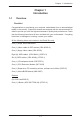
Preface Preface About This Manual This manual is written for system integrators, PC technicians and knowledgeable PC users. It provides information for the installation and use of the X7DCL-3/X7DCL-i motherboard. The X7DCL-3/X7DCL-i supports dual Intel Xeon Quad Core/Dual Core 5400/5300/5200/5100 Series processors (w/771 LGA) with a front side bus speed of up to 1.333 GHz.
X7DCL-3/X7DCL-i User's Manual Table of Contents Preface About This Manual ............................................................................................ iii Manual Organization . ....................................................................................... iii Conventions Used in the Manual........................................................................ iii Chapter 1: Introduction 1-1 Overview . ..............................................................................
Table of Contents Power Button .......................................................................................... 2-13 2-5 Connecting Cables ........................................................................................ 2-14 ATX Power Connector ........................................................................... 2-14 Processor Power Connector .................................................................. 2-14 Universal Serial Bus (USB)...........................................
X7DCL-3/X7DCL-i User's Manual Chapter 3: Troubleshooting 3-1 Troubleshooting Procedures ........................................................................... 3-1 Before Power On........................................................................................ 3-1 No Power.................................................................................................... 3-1 No Video ...................................................................................................
Chapter 1: Introduction 1-1 Chapter 1 Introduction Overview Checklist Congratulations on purchasing your computer motherboard from an acknowledged leader in the industry. Supermicro boards are designed with the utmost attention to detail to provide you with the highest standards in quality and performance. Check that the following items have all been included with your motherboard. If anything listed here is damaged or missing, contact your retailer.
X7DCL-3/X7DCL-i User's Manual Contacting Supermicro Headquarters Address: Super Micro Computer, Inc. 980 Rock Ave. San Jose, CA 95131 U.S.A. Tel: +1 (408) 503-8000 Fax: +1 (408) 503-8008 Email: marketing@supermicro.com (General Information) support@supermicro.com (Technical Support) Web Site: www.supermicro.com Europe Address: Super Micro Computer B.V. Het Sterrenbeeld 28, 5215 ML 's-Hertogenbosch, The Netherlands Tel: +31 (0) 73-6400390 Fax: +31 (0) 73-6416525 Email: sales@supermicro.
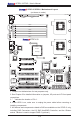
Chapter 1: Introduction X7DCL-3/X7DCL-i Image Note: The drawings and pictures shown in this manual were based on the latest PCB Revision available at the time of publishing of the manual. The motherboard you’ve received may or may not look exactly the same as the graphics shown in the manual.
X7DCL-3/X7DCL-i User's Manual X7DCL-3/X7DCL-i Motherboard Layout JPW1 8-Pin PWR SMB_PS JPW2 24-Pin PWR CPU1 VRM OH LED LED5 JKM1 USB0/1 KB/MS JAR Fan 1 JPI2C1 (not drawn to scale) JPWF1 JBS1 COM1 DIMM2A DIMM1A JCOM1 JVGA1 DIMM1B CPU1 DIMM2B VGA DIMM2C DIMM1C LAN1 X7DCL-3/i JLAN1 CPU2 LAN2 JPL2 LAN CTRL Intel 5100 North Bridge JIBTN1 I-Button Fan 3 Notes: SATA1 SATA0 SATA2 SATA3 SATA4 SATA5 CTRL J9 Floppy JFDD1 BPI2C JUSB2 SAS6 SAS7 SAS5 USB2/3 SAS4 USB4/5 SAS3
Chapter 1: Introduction Quick Reference (X7DCL-3/X7DCL-i) Jumper JBT1 2 2 JI C1/JI C2 JPG1 JPA1 (Note) JPA2 (Note) JPL1/ JPL2 JWD Description CMOS Clear SMB to PCI/PCI-Exp Slots VGA Enable SAS Enable Software RAID/IT RAID Mode GLAN1/GLAN2 Enable Watch Dog Default Setting See Chapter 2 Open (Disabled) Pins 1-2 (Enabled) Pins 1-2 (Enabled) Closed (Software RAID) Pins 1-2 (Enabled) Pins 1-2 (Reset) Connector BPI2C COM1/COM2 FAN 1-6 Floppy FP Control IDE J7/J8/9/10
X7DCL-3/X7DCL-i User's Manual Motherboard Features CPU • Dual Intel ® 64-bit Xeon LGA 771 Quad Core/Dual Core 5400/5300/5200/5100 Series processors at a front side bus speed of 1333 MHz/1066 MHz Memory • Six 240-pin DIMM sockets with support up to 32 GB Single-Rank, Registered/ ECC DDR2 667/533 Memory. Note: PCB revision 1.1a and later will now support up to 48 GBs of SingleRank, Registered/ECC DDR2 667/533 Memory (See Section 2-3 in Chapter 2 for DIMM Slot Population.
Chapter 1: Introduction • • Chassis intrusion detection System resource alert via Supero Doctor III ACPI Features • Slow blinking LED for suspend state indicator • • • Main switch override mechanism ACPI Power Management Power-on mode for power recovery Onboard I/O • Six SATA ports support RAID 0, 1, 10 and 5 (in the Windows OS environment) • Eight SAS ports supports RAID 0, 1, 10 and 5. (For X7DCL-3 only) • One SIMLC IPMI 2.
X7DCL-3/X7DCL-i User's Manual PROCESSOR#1 PROCESSOR#2 3.0 Gb/S LSI 1068E #0-3 #0-2 #0-1 PCI-EXP x8 PORT #2,3 PORT #4,5 PCI-EXP x8 PORT #6,7 DDR2 667 PCI-EXP x8 #1-3 #1-2 #1-1 MCH Intel 5100 PORT #0 PCIE X4 SAS #7 #6 #5 #4 #3 #2 #1 #0 ISL6312A 1067/1333 MT/S DDR2 667 PCI-E x8 PCI-E x8 1067/1333 MT/S RJ45 82573V PCI-EXP x1 #5 #4 #3 #2 #1 #0 DMI LANE5 3.0 Gb/S 82573L PCI-EXP x1 PCI-E x8 Slot PCI-E x4Signal RJ45 LANE6 ICH9R LANE1/2/3/4 #5 #4 #3 #2 #1 #0 USB 2.
Chapter 1: Introduction 1-2 Chipset and Processor Features Overview Built upon the functionality and the capability of the Intel 5100 chipset, the X7DCL3/X7DCL-i motherboard provides the performance and feature set required for dual processor-based high-end servers with configuration options optimized for intensive computing, high energy-efficiency and complex business applications.
X7DCL-3/X7DCL-i User's Manual 1-3 Special Features Recovery from AC Power Loss BIOS provides a setting for you to determine how the system will respond when AC power is lost and then restored to the system. You can choose for the system to remain powered off (in which case you must hit the power switch to turn it back on) or for it to automatically return to a power-on state. See the Power Lost Control setting in the Advanced BIOS Setup section to change this setting. The default setting is Last State.
Chapter 1: Introduction you can be alerted of the potential problem. You can also configure Supero Doctor to provide you with warnings when the system temperature goes beyond a predefined range. 1-5 ACPI Features ACPI stands for Advanced Configuration and Power Interface. The ACPI specification defines a flexible and abstract hardware interface that provides a standard way to integrate power management features throughout a PC system, including its hardware, operating system and application software.
X7DCL-3/X7DCL-i User's Manual to a minimum and users are not interrupted. The motherboard has a 3-pin header (WOL) to connect to the 3-pin header on a Network Interface Card (NIC) that has WOL capability. In addition, an onboard LAN controller can also support WOL without any connection to the WOL header. The 3-pin WOL header is to be used with a LAN add-on card only. Note: Wake-On-LAN requires an ATX 2.01 (or above) compliant power supply.
Chapter 1: Introduction The Super I/O provides functions that comply with ACPI (Advanced Configuration and Power Interface), which includes support of legacy and ACPI power management through an SMI or SCI function pin. It also features auto power management to reduce power consumption.
X7DCL-3/X7DCL-i User's Manual Notes 1-14
Chapter 2: Installation Chapter 2 Installation 2-1 Static-Sensitive Devices Electro-Static Discharge (ESD) can damage electronic components. To prevent damage to your system board, it is important to handle it very carefully. The following measures are generally sufficient to protect your equipment from ESD. Precautions • Use a grounded wrist strap designed to prevent static discharge. • Touch a grounded metal object before removing the board from the antistatic bag.
X7DCL-3/X7DCL-i User's Manual 2-2 Processor and Heatsink Fan Installation ! When handling the processor package, avoid placing direct pressure on the label area of the fan. Notes: • Always connect the power cord last and always remove it before adding, removing or changing any components. Make sure that you install the processor into the CPU socket before you install the CPU heatsink. • Intel's boxed Xeon CPU package contains the CPU fan and heatsink assembly.
Chapter 2: Installation Loading the Processor into the Socket 1. North Center Edge Use your thumb and your index finger to hold the CPU at the North Center Edge and the South Center Edge of the CPU. 2. 3. 4. 5. Align CPU Pin1 (the CPU corner marked with a triangle) against the socket corner that is marked with a triangle cutout.
X7DCL-3/X7DCL-i User's Manual Installing the Heatsink 1. Do not apply any thermal grease to the heatsink or the CPU die; the required CEK Passive Heatsink amount has already been applied. 2. 3. 4. Place the heatsink on top of the CPU so that the four mounting holes are aligned with those on the retention mechanism. Screw in two diagonal screws (ie the #1 and the #2 screws) until just snug (do not fully tighten the screws to avoid possible damage to the CPU.
Chapter 2: Installation 4. Clean the sur face of the CPU and the heatsink to get rid of the old thermal grease. Reapply the proper amount of thermal grease on the surface before you re-install the CPU and the heatsink. Mounting the Motherboard in the Chassis All motherboards have standard mounting holes to fit different types of chassis. Make sure that the locations of all the mounting holes for both motherboard and chassis match. Make sure that the metal standoffs click in or are screwed in tightly.
X7DCL-3/X7DCL-i User's Manual Memory Support The X7DCL-3/X7DCL-i supports up to 48 GB Single-Rank/Dual Rank, Registered ECC DDR2 667/533 in 6 DIMMs (The amount and type of memory supported is dependent on the PCB revision. See Note 1 Below). Populating DIMM slots with pairs of memory modules of the same size and same type will result in Interleaved Memory which will improve memory performance. Note 1: For the PCB Rev. 1.
Chapter 2: Installation Possible System Memory Allocation & Availability System Device Size Physical Memory Remaining (-Available) (4 GB Total System Memory) Firmware Hub flash memory (System BIOS) 1 MB 3.99 Local APIC 4 KB 3.99 Area Reserved for the chipset 2 MB 3.99 I/O APIC (4 Kbytes) 4 KB 3.99 PCI Enumeration Area 1 256 MB 3.76 PCI Express (256 MB) 256 MB 3.51 PCI Enumeration Area 2 (if needed) -Aligned on 256MB boundary- 512 MB 3.01 VGA Memory 16 MB 2.85 TSEG 1 MB 2.
X7DCL-3/X7DCL-i User's Manual 2-4 Control Panel Connectors/IO Ports The I/O ports are color coded in conformance with the PC 99 specification. See the figure below for the colors and locations of the various I/O ports. Back Panel Connectors/IO Ports X7DCL-3/i 2 4 1 3 5 6 Back Panel I/O Port Locations and Definitions Back Panel Connectors 1. Keyboard (Purple) 2. PS/2 Mouse (Green) 3. Back Panel USB Port 0 4. Back Panel USB Port 1 5. COM Port 1 (Turquoise) 6. VGA Port (Blue) 7. Gigabit LAN 1 8.
Chapter 2: Installation Front Control Panel JF1 contains header pins for various buttons and indicators that are normally located on a control panel at the front of the chassis. These connectors are designed specifically for use with Super Micro server chassis. See the figure below for the descriptions of the various control panel buttons and LED indicators. Refer to the following section for descriptions and pin definitions.
X7DCL-3/X7DCL-i User's Manual Front Control Panel Pin Definitions NMI Button The non-maskable interrupt button header is located on pins 19 and 20 of JF1. Refer to the table on the right for pin definitions. NMI Button Pin Definitions (JF1) Pin# Definition 19 Control 20 Ground Power LED Power LED Pin Definitions (JF1) The Power LED connection is located on pins 15 and 16 of JF1. Refer to the table on the right for pin definitions. Pin# Definition 15 +5V 16 Ground A. NMI B.
Chapter 2: Installation HDD LED The HDD LED connection is located on pins 13 and 14 of JF1. Attach a HDD LED Pin Definitions (JF1) hard drive LED cable here to display disk activity (for any hard drives on the system, including SAS, Serial ATA and IDE). See the table on the right for pin definitions.
X7DCL-3/X7DCL-i User's Manual Overheat/Fan Fail LED (OH) OH/Fan Fail LED Pin Definitions (JF1) Connect an LED to the OH/Fan Fail connection on pins 7 and 8 of JF1 to provide advanced warnings of chassis overheating or fan failure. Refer to the table on the right for pin definitions. Power Fail LED The Power Fail LED connection is located on pins 5 and 6 of JF1. Refer to the table on the right for pin definitions.
Chapter 2: Installation Reset Button The Reset Button connection is located on pins 3 and 4 of JF1. Attach it to the hardware reset switch on the computer case. Refer to the table on the right for pin definitions. Reset Button Pin Definitions (JF1) Pin# Definition 3 Reset 4 Ground Power Button The Power Button connection is located on pins 1 and 2 of JF1. Momentarily contacting both pins will power on/off the system.
X7DCL-3/X7DCL-i User's Manual 2-5 Connecting Cables ATX Power 24-pin Connector Pin Definitions ATX Power Connector A 24-pin main power supply connector is located at JPW2, and an 8-pin CPU PWR connector is locatged at JPW1 on the motherboard. These power connectors meet the SSI EPS 12V specification. See the table on the right for pin definitions. For the 8-pin PWR (JPW1), refer to the item below. Processor Power Connector Pin# Definition 13 +3.3V 1 +3.3V 14 -12V 2 +3.
Chapter 2: Installation Universal Serial Bus (USB) Back Panel USB (0/1) Pin Definitions There are six USB 2.0 (Universal Serial Bus) ports/headers on the motherboard. Two of them are Back Panel USB ports (USB#0/1: JPUSB1), and the other four are Front Panel USB connectors (USB#2/3: JUSB2), or Front-Accessible USB headers (USB#4/#5: JUSB3). See the tables on the right for pin definitions.
X7DCL-3/X7DCL-i User's Manual Fan Headers The X7DCL-3/X7DCL-i has four chassis/ system fan headers (Fan3 to Fan6), and Fan Header Pin Definitions (Fan1-6) two CPU Fans (Fans 1/2). All these fans are 4-pin fans. However, Pins 1-3 of the fan headers are backward compatible with the traditional 3-pin fans. See the table on the right for pin definitions. Note: The onboard fan speeds are controlled by Thermal Management via BIOS Hardware Monitoring in the Advanced Setting. (The default setting is Disabled.
Chapter 2: Installation ATX PS/2 Keyboard and PS/2 Mouse Ports PS/2 Keyboard and Mouse Port Pin Definitions The ATX PS/2 keyboard and the PS/2 mouse are located at JKM1. See the table on the right for pin definitions. (The mouse port is above the keyboard port.) See the table on the right for pin definitions.
X7DCL-3/X7DCL-i User's Manual Wake-On-Ring The Wake-On-Ring header is located at JWOR1. This feature allows Wake-On-Ring Pin Definitions your computer to receive and be "awakened" by an incoming call to the modem when the system is in the suspend state. See the table on the right for pin definitions. You must have a Wake-On-Ring card and cable to use this feature.
Chapter 2: Installation GLAN 1/2 (Giga-bit Ethernet Ports) Two G-bit Ethernet ports are located at JLAN1 and JLAN2 on the I/O backplane. These ports accept RJ45 type cables. GLAN1 GLAN2 Power LED/Speaker On the JD1 header, pins 1-3 are for a power LED, and pins 4-7 are for the speaker. See the table on the right for speaker pin definitions. Note: The speaker connector pins are for use with an external speaker. If you wish to use the onboard speaker, you should close pins 6-7 with a jumper.
X7DCL-3/X7DCL-i User's Manual Alarm Reset If three power supplies are installed, the system will notify you when any of Alarm Reset Pin Definitions the three power modules fails. Connect JAR1 to a micro-switch to turn off the alarm that is activated when a power module fails. See the table on the right for pin definitions. Pin Setting Definition Pin 1 Ground Pin 2 +5V PWR Supply Failure/PWR Fault Detect The system can notify you in the event of a power supply failure.
Chapter 2: Installation VGA Connector A VGA connector (JVGA) is located next to the COM1 port on the IO backplane. Refer to the board layout below for the location. GPIO Headers Four GPIO (Serial Links General Purpose Input/Output) headers are located at J7, J8, J9, J10 on the motherboard. These headers are used to communicate with the Seriel-Links System Monitoring chip on the backplane. J7 and J8 are used to monitor SATA activities, J9 and J10 are used to monitor SAS connections.
X7DCL-3/X7DCL-i User's Manual Power SMB (I2C) Connector PWR SMB Pin Definitions Power SMB (I 2 C) Connector (JPIC1) monitors the status of the power supply, Pin# Definition fan and system temperature. See the table on the right for pin definitions. 1 Clock 2 Data 3 PWR Fail 4 Ground 5 +3.3V BP PWR SMB Pin Definitions BP PWR SMB (I2C) Connector Pin# Backplane Power SMB (I2C) Connector (J5) monitors power supply of backplane IO connectors. See the table on the right for pin definitions.
Chapter 2: Installation Keylock Keylock Pin Definitions The keyboard lock connection is designated JKEY1. Utilizing this header allows Pin# Definition you to inhibit any actions made on the keyboard, effectively "locking" it.
X7DCL-3/X7DCL-i User's Manual 2-6 Jumper Settings Explanation of Jumpers Connector Pins To m o d i f y t h e o p e r a t i o n o f t h e motherboard, jumpers can be used to choose between optional settings. Jumpers create shorts between two pins to change the function of the connector. Pin 1 is identified with a square solder pad on the printed circuit board. See the motherboard layout pages for jumper locations.
Chapter 2: Installation CMOS Clear JBT1 is used to clear CMOS. Instead of pins, this "jumper" consists of contact pads to prevent the accidental clearing of CMOS. To clear CMOS, use a metal object such as a small screwdriver to touch both pads at the same time to short the connection. Always remove the AC power cord from the system before clearing CMOS. Note: For an ATX power supply, you must completely shut down the system, remove the AC power cord and then short JBT1 to clear CMOS.
X7DCL-3/X7DCL-i User's Manual VGA Enable/Disable VGA Enable/Disable Jumper Settings JPG1 allows you to enable or disable the VGA port. The default position is on pins Both Jumpers Definition 1 and 2 to enable VGA. See the table on the right for jumper settings. Pins 1-2 Enabled (Default) Pins 2-3 Disabled I C Bus to PCI/PCI-Exp. Slots 2 2 I2C to PCI/PCI-Exp. Slots Jumper Settings 2 Jumpers JPI C1/JPI C2 allow you to connect the System Management Bus 2 (I C) to PCI/PCI-Exp. slots.
Chapter 2: Installation SAS Enable/Disable JPA1 allows you to enable or disable SAS Connectors. The default position is SAS Enable/Disable Jumper Settings on pins 1 and 2 to enable SAS. See the table on the right for jumper settings. Jumper Settings (Note: This feature is available on the X7DCL-3 only.) Definition Pins 1-2 Enabled (Default) Pins 2-3 Disabled Software RAID Enable JPA2 allows you to select the SAS RAID mode. You can use either Software RAID or IT RAID.
X7DCL-3/X7DCL-i User's Manual 2-7 Onboard LED Indicators GLAN LEDs Link Activity LED LED Rear View (when viewing from the back of the chassis.) There are two GLAN ports on the motherboard. Each Gigabit Ethernet LAN port has two LEDs. The yellow LED indicates activity, while the power LED may be green, orange or off to indicate the speed of the connection. See the tables at right for more information.
Chapter 2: Installation System Status LED (LED4) Status LED Indicator Settings A Status LED Indicator is located at LED4 on the motherboard. This LED displays different colors to show the status of the system. Refer to the table on the right for system status. See the layout below for the LED location.
X7DCL-3/X7DCL-i User's Manual SAS LED Indicator (LED1) A SAS LED is located at LED1 on the motherboard. This LED indicates the status SAS LED Indicator Settings of SAS connections. Refer to the table on the right for LED1 settings. See the layout below for the LED location.
Chapter 2: Installation 2-8 Floppy Drive, SIMLC IPMI and Hard Disk Drive Connections Note the following when connecting the floppy and hard disk drive cables: • The floppy disk drive cable has seven twisted wires. • A red mark on a wire typically designates the location of pin 1. Floppy Drive Connector Pin Definitions (Floppy) Floppy Connector The floppy connector is located at JFDD1. See the table below for pin definitions.
X7DCL-3/X7DCL-i User's Manual IDE Connector IDE Drive Connector Pin Definitions An IDE Connector is located at JIDE1 on the motherboard. This motherboard uses the ITE IT8213F Controller. An IDE Driver is required for the IDE drive to function properly. See the table on the right for pin definitions. SIMLC IPMI Slot A Low Profile SIMLC IPMI Slot is located on the motherboard. Refer to the layout below for the IPMI Slot location.
Chapter 3: Troubleshooting Chapter 3 Troubleshooting 3-1 Troubleshooting Procedures Use the following procedures to troubleshoot your system. If you have followed all of the procedures below and still need assistance, refer to the ‘Technical Support Procedures’ and/or ‘Returning Merchandise for Service’ section(s) in this chapter. Note: Always disconnect the power cord before adding, changing or installing any hardware components. Before Power On 1.
X7DCL-3/X7DCL-i User's Manual supplies ~3VDC. If it does not, replace it with a new one. 3. If the above steps do not fix the Setup Configuration problem, contact your vendor for repairs. NOTE If you are a system integrator, VAR or OEM, a POST diagnostics card is recommended. For I/O port 80h codes, refer to App. B. Memory Errors 1. Make sure the DIMM modules are properly and fully installed. Check if DIMMs of different speeds or types have been installed.
Chapter 3: Troubleshooting • System configuration • An example of a Technical Support form is on our web site at http://www. supermicro.com/support/contact.cfm/. • Distributors: For immediate assistance, please have your account number ready when placing a call to our technical support department. We can be reached by e-mail at support@supermicro.com or by fax at: (408) 503-8000, option 2.
X7DCL-3/X7DCL-i User's Manual ( Warning: Do not shut down or reset the system while updating BIOS to prevent possible system boot failure!) Question: What's on the CD that came with my motherboard? Answer: The supplied compact disc has quite a few drivers and programs that will greatly enhance your system. We recommend that you review the CD and install the applications you need. Applications on the CD include chipset drivers for the Windows OS, and security and audio drivers.
Chapter 4: BIOS 4-1 Chapter 4 BIOS Introduction This chapter describes the Phoenix BIOS™ Setup utility for the X7DCL-3/X7DCL-i. Phoenix ROM BIOS is stored in a flash chip and can be easily upgraded using a floppy disk-based program. Note: Due to periodic changes to the BIOS, some settings may have been added or deleted and might not yet be recorded in this manual. Please refer to the Manual Download area of the Super Micro web site
X7DCL-3/X7DCL-i User's Manual 4-2 Running Setup Default settings are in bold text unless otherwise noted. The BIOS setup options described in this section are selected by choosing the appropriate text from the main BIOS Setup screen. All displayed text is described in this section, although the screen display is often all you need to understand how to set the options. When you first power on the computer, Phoenix BIOS™ is immediately activated.
Chapter 4: BIOS Main BIOS Setup Menu Main Setup Features System Time To set the system date and time, key in the correct information in the appropriate fields. Then press the key to save the data. System Date Using the arrow keys, highlight the month, day and year fields, and enter the correct data. Press the key to save the data. BIOS Date This item displays the date when this version of BIOS was built.
X7DCL-3/X7DCL-i User's Manual SATA Port 1 ~ SATA Port 6, Ext. Primary Master/Slave These settings allow the user to set the parameters of the slots indicated above. Press to activate the following submenu screen for detailed options of these items. Set the correct configurations accordingly. The items included in the submenu are: Type This option allows the user to select the type of IDE hard drive.
Chapter 4: BIOS 32 Bit I/O This option allows the user to enable or disable the function of 32-bit data transfer. The options are Enabled and Disabled. Transfer Mode This option allows the user to set the transfer mode. The options are Standard, Fast PIO1, Fast PIO2, Fast PIO3, Fast PIO4, FPIO3/DMA1 and FPIO4/DMA2. Ultra DMA Mode This option allows the user to select Ultra DMA Mode. The options are Disabled, Mode 0, Mode 1, Mode 2, Mode 3, Mode 4, and Mode 5.
X7DCL-3/X7DCL-i User's Manual SATA AHCI Enable Select Enable to enable the function of Serial ATA Advanced Host Interface. (Take caution when using this function. This feature is for advanced programmers only.The options are Enabled and Disabled.) System Memory This display informs you how much system memory is detected by the BIOS. Extended Memory This display informs you how much extended memory is detected by the BIOS.
Chapter 4: BIOS 4-4 Advanced Setup Choose Advanced from the Phoenix BIOS Setup Utility main menu with the arrow keys. You should see the following display. The items with a triangle beside them have sub menus that can be accessed by highlighting the item and pressing . Boot Features Access the submenu to make changes to the following settings. QuickBoot Mode If enabled, this feature will speed up the POST (Power On Self Test) routine by skipping certain tests after the computer is turned on.
X7DCL-3/X7DCL-i User's Manual Power Button Behavior If set to Instant-Off, the system will power off immediately as soon as the user hits the power button. If set to 4-sec., the system will power off when the user presses the power button for 4 seconds or longer. The options are instant-off and 4-sec override. Resume On Modem Ring Select On to “wake your system up” when an incoming call is received by your modem. The options are On and Off.
Chapter 4: BIOS Cache Base 0-512K If enabled, this feature will allow the data stored in the base memory area: block 0-512K to be cached (written) into a buffer, a storage area in the Static DROM (SDROM) or to be written into L1, L2 cache inside the CPU to speed up CPU operations. Select Uncached to disable this function. Select Write Through to allow data to be cached into the buffer and written into the system memory at the same time.
X7DCL-3/X7DCL-i User's Manual PCI Configuration Access the submenu to make changes to the following settings for PCI devices. Onboard GLAN-1/Onboard GLAN-2 (Gigabit- LAN) OPROM Configure Select Enabled to allow the system to boot from the GLAN-1 connection or the GLAN-2 connection. The options are Disabled and Enabled. Onboard Storage OPROM Configure Select Enabled to allow the system to boot from the onboard storage device. The options are Disabled and Enabled.
Chapter 4: BIOS Advanced Chipset Control Access the submenu to make changes to the following settings. Warning: Take Caution when changing the Advanced settings. An incorrect setup, a very high DRAM frequency or an incorrect DRAM timing may cause the system become unstable. When this occurs, reset the setting to the default setting. Accelerate MRC If Enabled, the BIOS will skip MRC calculation if there aren't any changes in DIMM population. The options are Enabled and Disabled.
X7DCL-3/X7DCL-i User's Manual Demand Scrubbing Scrubbing is a process that allows the North Bridge to correct correctable memory errors found on a memory module. When the CPU or I/O issues a demand- read command, and the read data from memory turns out to be a correctable error, the error is corrected and sent to the requestor (the original source). Memory is updated as well. Select Enabled to use Demand Scrubbing for ECC memory correction.
Chapter 4: BIOS Core-Multi-Processing (Available if supported by the CPU.) Set to Enabled to use a processor's Second Core and beyond. (Please refer to Intel's web site for more information.) The options are Disabled and Enabled. Machine Checking (Available when supported by the CPU.) Set to Enabled to activate the function of Machine Checking and allow the CPU to detect and report hardware (machine) errors via a set of model-specific registers (MSRs). The options are Disabled and Enabled.
X7DCL-3/X7DCL-i User's Manual Intel ® Virtualization Technology (Available if supported by the CPU.) Select Enabled to use the feature of Virtualization Technology to allow one platform to run multiple operating systems and applications in independent partitions, creating multiple "virtual" systems in one physical computer. The options are Enabled and Disabled. Note: If there is any change to this setting, you will need to power off and restart the system for the change to take effect.
Chapter 4: BIOS Base I/O Address This setting allows you to select the base I/O address for Serial Port A. The options are 3F8, 2F8, 3E8, and 2E8. Interrupt This setting allows you to select the IRQ (interrupt request) for Serial Port A. The options are IRQ3 and IRQ4. Serial Port B This setting allows you to decide how Serial Port B is controlled.The options are Enabled (user defined), Disabled, Auto (BIOS controlled) and OS Controlled.
X7DCL-3/X7DCL-i User's Manual Event Logging This setting allows you to Enable or Disable event logging. ECC Event Logging This setting allows you to Enable or Disable ECC event logging. Mark DMI Events as Read Highlight this item and press to mark the DMI events as read. Clear All DMI Event Logs Select Yes and press to clear all DMI event logs. The options are Yes and No. Console Redirection Access the submenu to make changes to the following settings.
Chapter 4: BIOS Hardware Monitor Highlight an item and hit to see the status of each of the following items: CPU Overheat Alarm This option allows the user to select the CPU Overheat Alarm setting which determines when the CPU OH alarm will be activated to provide warning of possible CPU overheat. Refer to the the next item, CPU Temperature for more information regarding PECI, DTS and other thermal features of this motherboard.
X7DCL-3/X7DCL-i User's Manual High – The processor is running hot. This is a ‘caution’ level since the CPU’s ‘Temperature Tolerance’ has been reached (or has been exceeded) and may activate an overheat alarm: The Default Alarm – the Overheat LED and system buzzer will activate if the High condition continues for some time after it is reached. The CPU fan will run at full speed to bring the CPU temperature down.
Chapter 4: BIOS Fan1-Fan6 Speeds If the feature of Auto Fan Control is enabled, the BIOS will automatically display the status of the fans indicated in this item. Fan Speed Control Modes This feature allows the user to decide how the system controls the speeds of the onboard fans. The CPU temperature and the fan speed are correlative. When the CPU on-die temperature increases, the fan speed will also increase, and vise versa. If the option is set to 3-pin fan, the fan speed is controlled by voltage.
X7DCL-3/X7DCL-i User's Manual IPMI (The option is available only when an IPMI card is installed in the system.) IPMI Specification Version: This item displays the current IPMI Version. BMC Hardware/Firmware Version: This item displays the current Firmware Version. System Event Logging Select Enabled to enable IPMI Event Logging. When this function is set to Disabled, the system will continue to log events received via system interface. The options are Enabled and Disabled.
Chapter 4: BIOS BIOS POST Watch Dog Set to Enabled to enable POST Watch Dog. The options are Enabled and Disabled. OS Boot Watch Dog Set to Enabled to enable OS Boot Watch Dog. The options are Enabled and Disabled. Timer for Loading OS (Minutes) This feature allows the user to set the time value (in minutes) for the previous item: OS Boot Watch Dog by keying-in a desired number in the blank. The default setting is 10 (minutes.) (Please ignore this option when OS Boot Watch Dog is set to "Disabled".
X7DCL-3/X7DCL-i User's Manual Realtime Sensor Data This feature display information from motherboard sensors, such as temperatures, fan speeds and voltages of various components. IPMI LAN Configuration VLAN Tagging Select Enabled to enable Virtual LAN(s) for IPMI connections and allow the user to configure VLAN settings. The options are Enabled and Disabled. VLAN ID This item allows the user to change the VLAN ID. The default setting is 1h.
Chapter 4: BIOS 4-5 Security Choose Security from the Phoenix BIOS Setup Utility main menu with the arrow keys. You should see the following display. Security setting options are displayed by highlighting the setting using the arrow keys and pressing . All Security BIOS settings are described in this section. Supervisor Password Is: This indicates if a supervisor password has been entered for the system.
X7DCL-3/X7DCL-i User's Manual Password on Boot This setting allows you to determine if a password is required for a user to enter the system at bootup. The options are Enabled (password required) and Disabled (a password not required). 4-6 Boot Choose Boot from the Phoenix BIOS Setup Utility main menu with the arrow keys. You should see the following display. See details on how to change the order and specs of boot devices in the Item Specific Help window.
Chapter 4: BIOS 4-7 Exit Choose Exit from the Phoenix BIOS Setup Utility main menu with the arrow keys. You should see the following display. All Exit BIOS settings are described in this section. Exit Saving Changes Highlight this item and press to save any changes you have made and to exit the BIOS Setup utility. Exit Discarding Changes Highlight this item and press to exit the BIOS Setup utility without saving any changes you may have made.
Appendix A: POST Error Beep Codes Appendix A POST Error Beep Codes This section lists POST (Power On Self Test) error beep codes for the Phoenix BIOS. POST error beep codes are divided into two categories: recoverable and terminal. This section lists Beep Codes for recoverable POST errors. Recoverable POST Error Beep Codes When a recoverable type of error occurs during POST, BIOS will display a POST code that describes the problem.
X7DCL-3/X7DCL-i User's Manual Notes A-2
Appendix B: Installing the Windows OS Appendix B Installing the Windows OS After all hardware components have been installed, you must first configure Intel South Bridge RAID Settings before you install the Windows OS and other software drivers. To configure RAID settings, please refer to RAID Configuration User Guides posted on our website at www.supermicro.com/support/manuals. B-1 Installing the Windows XP/2000/2003 OS for Systems with RAID Functions 1.
X7DCL-3/X7DCL-i User's Manual B-2 Installing the Windows XP/2000/2003 OS for Systems without RAID Functions 1. Insert Microsoft's Windows XP/2000/2003 Setup CD in the CD Driver, and the system will start booting up from CD. 2. Continue with the OS installation. The Windows OS Setup screen will display. 3. From the Windows XP/2000/2003 Setup screen, press the key. The XP/2000/2003 Setup will automatically load all device files and then continue with the Windows XP/2000/2003 installation. 4.
Appendix C: Installing Other Software Programs and Drivers Appendix C Software Installation C-1 Installing other Drivers and the OS After you've installed the Windows Operating System, a screen as shown below will appear. You are ready to install software programs and drivers that have not yet been installed. To install these software programs and drivers, click the icons to the right of these items. Driver/Tool Installation Display Screen Notes: 1.
X7DCL-3/X7DCL-i User's Manual C-2 Configuring Supero Doctor III The Supero Doctor III program is a Web-based management tool that supports remote management capability. It includes Remote and Local Management tools. The local management is called the SD III Client. The Supero Doctor III program included on the CDROM that came with your motherboard allows you to monitor the environment and operations of your system.
Appendix C: Installing Other Software Programs and Drivers Supero Doctor III Interface Display Screen-II (Remote Control) Note: SD III Software can be downloaded from our Web site at: ftp://ftp. supermicro.com/utility/Supero_Doctor_III/. You can also download SDIII User's Guide at: http://www.supermicro.com/PRODUCT/Manuals/SDIII/UserGuide.pdf. For the Linux OS, we will still recommend that you use Supero Doctor II.
X7DCL-3/X7DCL-i User's Manual Notes C-4
(Disclaimer Continued) The products sold by Supermicro are not intended for and will not be used in life support systems, medical equipment, nuclear facilities or systems, aircraft, aircraft devices, aircraft/emergency communication devices or other critical systems whose failure to perform be reasonably expected to result in significant injury or loss of life or catastrophic property damage.